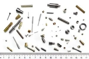
In the world of high-performance engineering—be it aerospace, medical devices, or semiconductor equipment—the difference between a successful assembly and a costly failure often lies in a few microns. As a design engineer, your CAD model is a masterpiece of intent; however, transitioning that intent into a physical component requires a deep understanding of Manufacturing Realities.
This guide explores the critical intersection of tight tolerances and Design for Manufacturing (DFM), helping you optimize performance while controlling production costs.
1. Defining the Limits: Standard vs. Precision Tolerances
While modern CNC centers are incredibly capable, “tightening the tolerance” isn’t always the answer. Every extra decimal point adds exponential cost and inspection time.
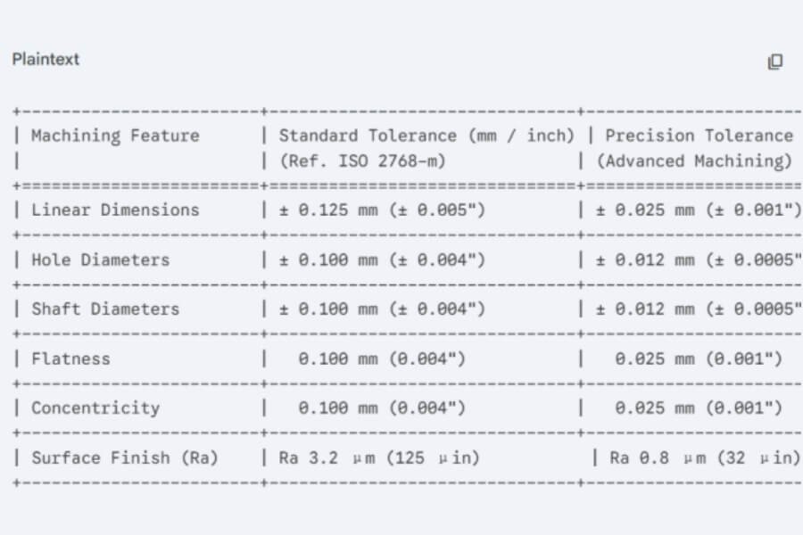
Standard Tolerances: Typically $\pm0.125mm$ ($0.005″$). Suitable for most non-mating features.
Precision Tolerances: $\pm0.025mm$ ($0.001″$) to $\pm0.010mm$ ($0.0004″$). Required for press fits, bearing seats, and high-speed rotating parts.
Pro Tip: Only apply tight tolerances to critical mating surfaces. Over-specifying non-critical dimensions is the #1 driver of unnecessary CNC machining costs.
2. The Variables: What Affects Your Final Dimensions?
Achieving sub-micron precision is a battle against physics. When we review your designs, our engineering team accounts for:
Thermal Expansion: Materials like Aluminum 6061 have a higher coefficient of thermal expansion than Stainless Steel 316. During high-speed cutting, the heat generated can cause the part to “grow,” leading to deviations once it cools.
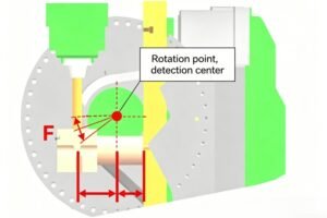
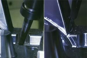
Tool Deflection: Long, slender end mills act like springs. If a feature requires a deep reach with a small diameter, the tool will “push away” from the work surface, resulting in tapers or “chatter” marks.
Workholding & Internal Stress: Removing large volumes of material can release internal stresses in the metal, causing the part to warp or “potato chip” after it is released from the vise.
3. Essential DFM Strategies for Engineers
To ensure your high-precision parts are “Right First Time,” consider these DFM optimizations before finalizing your STEP file:
A. Avoid Deep, Narrow Pockets
The ideal depth-to-width ratio for a pocket is 3:1 or less. If you must go deeper, expect wider tolerances due to the need for longer, less stable tooling.
B. Standardize Internal Radii
Always design internal corners with a radius slightly larger than the radius of the cutting tool. For example, if using a 6mm end mill, specify a 3.2mm or 3.5mm radius. This prevents the tool from “burying” into the corner, which reduces vibration and improves surface finish.
C. Simplify the Setup
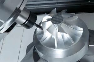
Every time a part is flipped or moved to a different fixture (Setup), the risk of “tolerance stack-up” increases. 5-axis CNC machining is the gold standard here, as it allows us to machine almost all faces in a single setup, maintaining perfect concentricity and position.
4. Quality Assurance: Measuring What Matters
Precision is meaningless if it cannot be verified. At Shenzhen Xinmingliang Technology, our quality protocol includes:
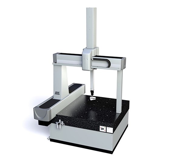
CMM (Coordinate Measuring Machine) Inspection for complex geometries.
Digital Micrometers and Air Gauges for bore diameters.
Surface Roughness Testers to ensure $Ra$ values meet your specifications.
Conclusion: Collaborative Engineering is the Key
High-precision CNC machining is not just about having the best machines; it’s about the synergy between the designer and the machinist. By incorporating DFM principles early in your design phase, you reduce lead times, eliminate scrap, and ensure your product performs exactly as intended.
Are you working on a project that requires tight tolerances?
[Upload your CAD files for a free DFM feedback and Quote]