
Which sheet metal cutting process should you specify? For most parts under 6 mm in aluminum or mild steel, the answer is fiber laser — and it is the wrong answer often enough that the exceptions are worth knowing before you write the purchase order.
The choice is not about which process is more accurate. It is about four physical facts: how wide the cut is, how much heat enters the part, how thick the material can be before the process stops working economically, and what shape the cut face comes out as.
Get those four right and the rest follows. Get them wrong and you will discover the problem at the bending station, when the parts crack along the cut edge or the flange does not sit flat.
This article lays the four processes side by side by thickness, tolerance, and heat, then ends with a table you can match against your drawing.
The Four Cutting Processes and What Each Does to the Edge
Each sheet metal cutting process leaves a different edge, and the edge determines what you can do next. The cutting routes we run sit inside our Sheet Metal Fabrication service line, as the first step in any cnc sheet metal fabrication job. Fiber laser gives a narrow, slightly tapered cut with a thin recast layer. Plasma gives a wider cut with a pronounced bevel and a heat-affected zone measured in tenths of a millimeter. Waterjet gives a near-vertical cut with no heat input at all. Shear gives a straight cut with a rolled edge and a burr on the underside.
That last point matters more than buyers expect. A sheared edge is work-hardened along the cut line, and if that edge later becomes a bend line on bent sheet metal, the material is already stiffer there and prone to cracking. Shearing is fast and cheap for straight blanks, but it constrains where cnc bending can put a flange.
Per ISO 9013, thermal cut quality is classified by perpendicularity and surface roughness, with the tightest class (range 4) requiring perpendicularity within 0.5 mm over the full thickness. That class is achievable with fiber laser on thin material and difficult with plasma.
Standalone conclusion: The four processes differ first by edge geometry, not by accuracy. Laser, plasma, waterjet, and shear each leave a different cut face, and that face constrains the next operation.

Cutting by Thickness: Where Each Process Stops Working
The economical thickness range is narrower than the specification sheet suggests. A machine’s maximum rated thickness is the point where it can still cut, not the point where it is worth running.
Under 3 mm, 3–6 mm, and over 6 mm
Below 3 mm, fiber laser dominates. Cutting speed is high, kerf is narrow, and the heat input is low enough that distortion stays manageable on flat parts. Plasma at this thickness produces a bevel that costs more to clean up than the cut saved.
Between 3 and 6 mm, laser still wins on aluminum and stainless but the advantage narrows. Plasma becomes competitive on mild steel at the upper end, particularly when the part has no tight tolerance callout on the cut edge.
Above 6 mm, the picture changes by material. Fiber laser on aluminum above roughly 6 mm becomes slow and prone to dross, because aluminum reflects the beam and conducts heat away quickly. Waterjet takes over for thick aluminum, stainless, and any material where heat cannot be tolerated. Plasma remains the economical choice for thick mild steel where edge quality is not critical.
| Thickness | Aluminum | Mild steel | Stainless |
|---|---|---|---|
| Under 3 mm | Fiber laser | Fiber laser | Fiber laser |
| 3–6 mm | Fiber laser | Laser or plasma | Fiber laser |
| Over 6 mm | Waterjet | Plasma or waterjet | Waterjet |
Standalone conclusion: Every process has an economical thickness ceiling below its rated maximum. Above 6 mm, aluminum and stainless generally move to waterjet, while thick mild steel stays with plasma.
Cutting by Tolerance and Kerf
Kerf is the material a sheet metal cutting operation removes, and it is the number most drawings omit. Fiber laser removes roughly 0.1 to 0.3 mm depending on thickness and assist gas. Plasma removes 1 to 3 mm. Waterjet removes 0.8 to 1.5 mm depending on nozzle and abrasive flow. Shear removes nothing but displaces material, which is why sheared blanks come out slightly longer than the layout.
That changes how you dimension a part. A laser-cut hole specified at Ø10.0 mm comes out at Ø10.0 mm because the toolpath is offset by half the kerf. A waterjet hole does too — but its achievable tolerance is wider, typically ±0.1 mm against ±0.05 mm for laser on thin sheet, because abrasive jet wander and nozzle wear are harder to control.
Taper matters for anything that has to fit through the hole. Laser taper on 3 mm stainless runs 0.05 to 0.15 mm per side depending on focus and gas; waterjet taper is larger and grows with thickness. With a dowel pin pressed into a cut hole, specify whether tolerance applies at the entry or exit face, or you will argue about it at incoming inspection.
Standalone conclusion: Kerf differs by an order of magnitude between processes, and tolerance must name which face it applies to. Waterjet taper grows with thickness; laser taper depends on focus and assist gas.
Heat Input and What It Does to the Part
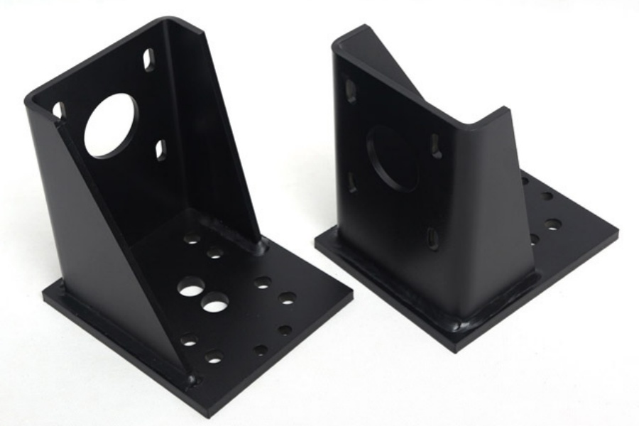
Heat is the hidden variable. Laser and plasma both put energy into the cut zone, and the heat-affected zone changes microstructure within a few tenths of a millimeter of the edge. For most parts this is irrelevant. It matters in three situations: when the cut edge will be bent, when the part will be anodized, and when the part sees cyclic loading.
When laser cutting changes the material
On 6061 aluminum, laser cutting leaves a narrow recast layer and a heat-affected zone extending 0.1 to 0.3 mm into the base metal. Form a sheet metal bend along that edge without relief and the recast layer — harder and more brittle than the base metal — becomes the crack initiation site. That is the most common cause of parts that pass dimensional inspection and fail at the press brake.
The anodizing problem is different. Anodizing grows the oxide from the base metal, and a heat-affected zone anodizes to a slightly different shade. On clear parts with a visible cut edge it shows as a faint line; on dark bronze and black it is usually invisible.
Waterjet avoids both issues because it introduces no heat. That is the main reason waterjet is specified for thick aluminum and for any part where the cut edge is also a cosmetic surface.
Standalone conclusion: Laser and plasma leave a heat-affected zone that changes how the cut edge bends, anodizes, and fatigues. Waterjet introduces no heat, which is why it is specified when the cut edge is also a functional or cosmetic surface.
Nesting, Tabs, and Handling Thin Sheet
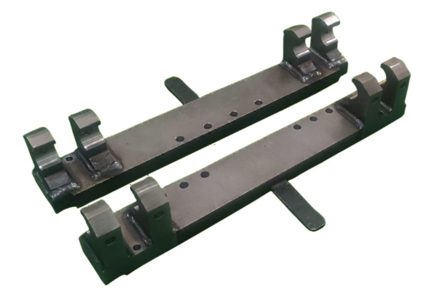
Thin sheet fails at the cutting table, not at the machine. Below about 1 mm, sheet metal parts tend to lift, vibrate, and tip into the kerf, and the fix is nesting rather than power settings.
Three techniques carry most of the load. Micro-tabs — uncut bridges of 0.3 to 0.8 mm that hold the part to the skeleton until it is snapped out. Common-line cutting, where adjacent parts share a cut line, halving cut length and heat input. And sequencing from the inside out, so the part never loses support before the last cut.
Tab placement is a design decision, not a machine setting. Put a tab where the snap-off burr will land on a non-cosmetic edge. Put it on a straight run, never on a corner or a hole perimeter, because a tab on a corner leaves a bump that has to be filed and filing a corner out of square is a rework operation.
Standalone conclusion: Thin-sheet quality is decided by nesting and tab placement, not by laser power. Tabs belong on straight non-cosmetic edges, never on corners or hole perimeters.
Cost Per Part: What Actually Drives It
Piece cost is not a function of cutting speed. It is a function of three quantities: nest utilization, pierce count, and total cut length. A shop quoting custom cut sheet metal by material area is quoting a proxy; one quoting by these three is quoting the actual cost. This is where sheet metal processing economics differ most from machining, where cycle time drives everything.
Nest utilization is the share of the sheet that becomes parts. A well-nested job on a standard 1,250 × 2,500 mm sheet runs 75 to 85 percent. A poorly nested job with a single part shape and awkward spacing can drop to 55 percent, and that lost 30 percent is material you paid for and scrapped.
Pierce count matters because every pierce costs time and consumable life. A part with 40 small holes has 40 pierces. Redesigning a 40-hole pattern into 12 slots reduces pierce count by 70 percent and often cuts piece cost more than switching processes would.
Cut length is the obvious one, but it interacts with thickness. Doubling thickness roughly halves cutting speed for laser, so cut length cost doubles twice. The processes we run in house are listed under CNC Machining Services.
Standalone conclusion: Piece cost is driven by nest utilization, pierce count, and cut length, not by cutting speed. Consolidating many small holes into fewer slots often saves more than changing processes.

Matching the Process to Your Drawing
Work down the drawing feature by feature and the process selects itself. Start with material and thickness, which eliminates most options immediately. Then check whether the cut edge is also a bend line or a cosmetic surface, because that is where heat becomes a problem. Then check the tightest tolerance on a cut feature. On a sheet metal cnc route the same logic holds, and the same questions will decide whether sheet metal folding should follow the cut or replace it.
Three questions decide it:
- What is the material and the thickness? Above 6 mm in aluminum or stainless, start with waterjet.
- Is the cut edge also a bend line or a visible surface? If yes, avoid laser on aluminum unless the bend is relieved or the edge is machined after cutting.
- What is the tightest tolerance on a cut feature, and does it apply at the entry or exit face? If it applies at both, specify a process that holds taper, or accept a wider band.
If two processes remain viable, choose on quantity and nest utilization rather than tolerance. At low volume setup and programming dominate; at high volume material utilization does. The equipment behind these metal cutting and bending services is described in About Us.
Standalone conclusion: Process selection follows from material, thickness, whether the cut edge is functional, and the tightest cut tolerance. When two processes remain viable, choose on quantity and nest utilization.

The four sheet metal cutting processes are not ranked. They occupy different thickness bands, leave different edges, and put different amounts of heat into the part. In sheet metal cutting, laser is the default for thin material, plasma for thick mild steel, waterjet for thick aluminum and stainless, and shear for straight blanks where the cut line never becomes a bend line.
The mistake worth avoiding is specifying by reputation instead of by the four facts. A part cut on the wrong process passes dimensional inspection and fails downstream — at the brake, at the anodizer, or in fatigue. On aluminum sheet metal fabrication that failure usually appears as a cracked bend, and it traces back to a cut that looked fine.
If you have a drawing and want the thickness and heat questions resolved against it, send it through our CNC Machining Quote Form and we will come back with the process route and the tolerance assessment on the cut features. Related guides on forming and finishing live on the Blog Homepage.