
Your first sheet metal prototype will not fit. Not because the shop made a mistake, and not because the drawing was wrong — because the flat pattern was calculated with a K-factor that does not match the material you actually bought.
This is the normal condition of prototyping, not a defect. Sheet metal behaves differently at every bend depending on alloy, temper, thickness, grain direction, and punch radius. A flat pattern is a prediction, and the first part is the measurement that corrects it. That is why rapid sheet metal work is judged on how fast the second iteration arrives, not on how good the first looks. You stop expecting the first article to be right and start designing the process so the second one is.
This article covers what sheet metal prototyping can build without hard tooling, how to correct the flat pattern from measured data, and what changes when the part moves to production. Most of it applies to any sheet metal prototype fabrication run, whether the shop calls it rapid sheet metal prototyping or ordinary first-article work.
Why Prototype Sheet Metal Is a Different Problem
A sheet metal prototyping run exists to answer a design question, not to prove a production rate. The forming and assembly work behind it sits under Sheet Metal Fabrication. That single difference justifies every unusual choice that follows: no hard dies, hand rework allowed, unit cost irrelevant, and dimensional accuracy secondary to fit and function.
The trap is applying production logic to a prototype. A buyer who negotiates the piece price on a five-part order, or insists on a dedicated die because it will be needed eventually, is optimizing the wrong variable. The die will be obsolete after the second design revision. The five parts exist to tell you what the second revision should be.
What actually matters at this stage is turnaround and the quality of the feedback. A shop that returns five parts in four days with a marked-up flat pattern and three notes about features that will not form is worth more than a shop that returns five parts in three weeks with no commentary.
Standalone conclusion: Prototyping optimizes for learning speed, not unit cost. The deliverable is a corrected flat pattern and design feedback, not five cheap parts.

Bending Without a Hard Die: Press Brake, Segmented Tooling, Hand Forming
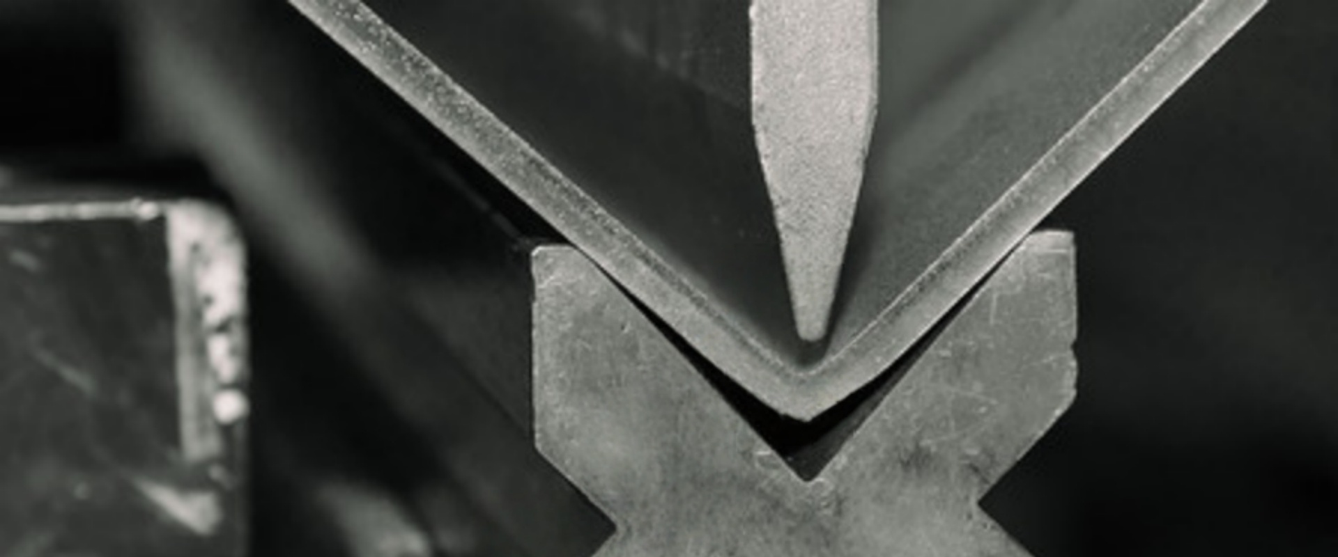
You do not need a dedicated die to bend sheet metal. Knowing how to bend sheet metal at prototype stage is mostly knowing what a standard press brake with a generic punch and multi-V die can do, and that is nearly any geometry. Segmented tooling lets you build an odd-shaped punch from standard sections in under an hour, so bending sheet metal without a hard die — sheetmetal bending, in the trade’s shorthand — is a scheduling question, not a capability one.
The limits are geometric. A standard gooseneck punch reaches about 100 mm of clearance before the part hits the ram; beyond that you need a taller punch, a different machine, or a sequence that forms the deepest flange last. Hand forming covers the rest — a soft mallet over a hardwood form, a slip roller for large radii, a shrinker-stretcher for curved flanges. Loose dimensions, correct geometry, the right trade at this stage.
When a formed or printed buck is enough
For parts where the shape matters more than the material, a 3D-printed or machined buck lets you check fit and clearance without any sheet metal work at all. Use it to confirm that the bracket sits where you think it sits, then form the real part once. This is faster than iterating in metal when the geometry is still moving.
Standalone conclusion: Standard press brake tooling and segmented punches cover most prototype geometry; hand forming covers the rest. A printed buck is the faster route when the shape is still changing.
Bend Allowance and Springback on a First Article
In sheet metal prototyping, bend allowance is the arc length of the neutral axis through the bend, and it turns a folded part into a flat pattern. The bending formula for sheet metal is BA = π (R + K·T) × θ / 180, where R is the inside radius, T is thickness, θ is the bend angle, and K is the neutral axis position as a fraction of thickness. Running that sheet metal bending calculation correctly is the whole game, and bend radius sheet metal limits decide whether it can be formed at all.
K is the problem. It is not a material constant; it depends on the R-to-T ratio, the forming method, and the temper. For air bending, K commonly falls between 0.33 and 0.50, with 0.44 as a starting assumption in much of the trade literature. On a 2 mm 5052 part with a 2 mm inside radius, that assumption gives a flat pattern that is close but rarely exact.
Springback compounds it. Aluminum 6061-T6 springs back roughly 1 to 3 degrees depending on R-to-T, and the part comes off the brake open. The shop compensates by overbending, and the amount of overbend is another number that has to be measured rather than assumed.
6061-T6 has elongation around 10 to 12 percent, and bending aluminum sheet metal in that temper to a tight inside radius — under roughly 2T — frequently produces cracking on the outside of the bend, especially across the grain. Prototype parts in 6061 are usually better made from 5052-H32, which forms at a 1T radius without cracking, or from 6061-O if the final part must be 6061 and will be heat treated afterward.
Standalone conclusion: Bend allowance depends on a K-factor that varies with R-to-T and temper, and 6061-T6 cracks at tight radii. Prototype in 5052-H32 unless the alloy is fixed by the design.
Back-calculating K-factor from one measured part
You do not need a test matrix. Measure the first part and solve for K.
- Measure the formed part’s overall length across the bend and the two flange lengths to the tangent points.
- Compare the sum of the flange lengths against the formed overall length. The difference is the bend deduction.
- Convert bend deduction to bend allowance using BD = 2 × OSSB − BA, where OSSB is the outside setback, (R + T) × tan(θ/2).
- Solve the bend allowance formula for K and use that value in the next flat pattern.
One part gives you a K within about 0.02 of the true value for that material and tooling combination. Two parts from different heats tighten it further. This is faster and more reliable than looking up a table, because the table was built for someone else’s press brake.
Cutting Prototypes: Laser, Waterjet, or Hand
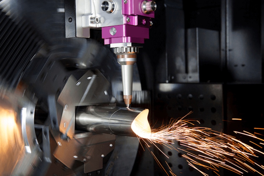
Cut with whatever changes fastest. Laser wins almost every time, because a revision means editing a program and re-running, with no tooling to modify.
The exception is thick or heat-sensitive material. Laser on aluminum above about 6 mm leaves a heat-affected zone that cracks if the cut edge is later bent, a common failure in prototype brackets. Waterjet avoids the heat but adds a day of scheduling. Hand cutting — shear, nibbler, jigsaw, files — is legitimate where the outline is not what you are testing, and it sits under CNC Machining Services alongside the machine routes. Validating a hole pattern leaves the profile free; validating the profile does not.
Standalone conclusion: Laser is the default for prototype cutting because revisions cost a program edit. Switch to waterjet when the cut edge will be bent in thick aluminum, since the heat-affected zone cracks there.
Fastening and Joining Before You Have a Production Process
Prototype joints are chosen for speed, and that choice quietly constrains the finish later. A riveted joint traps electrolyte in the gap when anodized and bleeds out over weeks; a spot weld leaves an electrode mark that shows through thin powder coat.
The three joints that survive finishing are: clinching (no fastener, no trapped chemistry), pressed-in fasteners installed after finishing, and structural adhesive on a properly prepared surface. If the prototype must be finished to evaluate color or texture, use one of those three.
Pem-style press-in fasteners need a hole sized to a specific tolerance and a squeeze force the shop must set up for. On a five-part prototype, hand-installed rivet nuts are adequate and far faster; specify press-in hardware on the production drawing, not the prototype.
Standalone conclusion: Prototype joining methods can make later finishing impossible. Clinching, post-finish pressed fasteners, and structural adhesive survive anodizing and powder coating; rivets and spot welds do not.
What Changes Between Prototype and Production
Four things change when a sheet metal prototyping project moves to volume, and three are invisible on the drawing. Tooling first: a generic punch becomes a dedicated die, and the flat pattern must be recalculated because the new tooling forms a different radius. Process sequence second, because a production line minimizes handling rather than setup. Inspection third, from full dimensional check on one part to sampling against a control plan. Unit cost last, and usually not as much as buyers expect once tooling amortization is included.
The risk is designing the production part around prototype behavior. If prototype sheet metal parts were made in 5052 because 6061 cracked, the production drawing must either keep 5052 or specify a bend radius 6061-T6 can survive — typically 2T to 3T depending on temper and grain direction.
| Element | Prototype | Production |
|---|---|---|
| Tooling | Generic or segmented punch, multi-V die | Dedicated die, fixed radius |
| Flat pattern | Recalculated from measured K after each iteration | Frozen and controlled as a process document |
| Process sequence | Ordered to minimize setup | Ordered to minimize handling |
| Inspection | Full dimensional check on one part | Sampling against a control plan |
| Unit cost | Irrelevant; measured in days | Driven by material utilization and cycle time |
| Alloy choice | Whatever forms without cracking | Fixed by the drawing, with bend radius matched to temper |
Standalone conclusion: Tooling, process sequence, inspection method, and unit cost all change at production, and the flat pattern changes with the tooling. Freeze the alloy and bend radius on the production drawing before releasing it.
What to Send and What You Get Back
Send a 3D model plus a PDF drawing with critical dimensions marked, the alloy and temper, the bend radius you want, and the surface finish. If the finish matters, say so at the start — it changes the joining method.
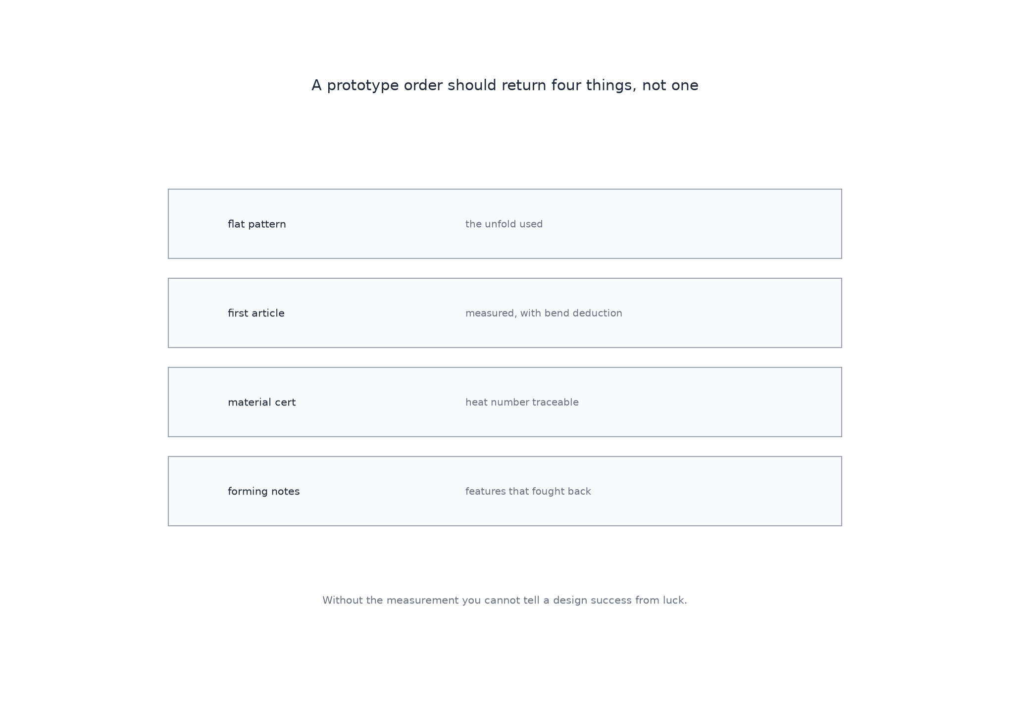
What you should get back is not just sheet metal prototypes. Ask for the flat pattern used, the measured first article with the bend deduction recorded, material certification, and a note on any feature that was difficult to form. The last item is the one that saves money on the next revision.
Our shop publishes its process capability in About Us, the number your flat pattern should be checked against. A prototype order without a first article report is one you cannot evaluate — parts that fit by accident still pass inspection.
Standalone conclusion: A prototype delivery should include the flat pattern, measured first article, material cert, and a note on hard-to-form features. Without the measurement, you cannot tell design success from luck.
Sheet metal prototyping without hard tooling is a solved problem. A press brake with generic or segmented tooling forms almost any geometry, laser cuts revisions in hours, and hand work fills the gaps. What is not solved is the flat pattern, and that is where prototype budgets go wrong.
Plan for the first part to be wrong. Measure it, solve for K, and rebuild. Two iterations is normal; three means the radius or the alloy is fighting you, and the answer is usually to change the alloy, not the tooling.
If you have a design that needs five parts before it needs five thousand, send the model and drawing through our CNC Machining Quote Form and we will return the flat pattern, the measured first article, and a note on what will change at volume. More forming and tolerance guides are collected on the Blog Homepage.