Introduction
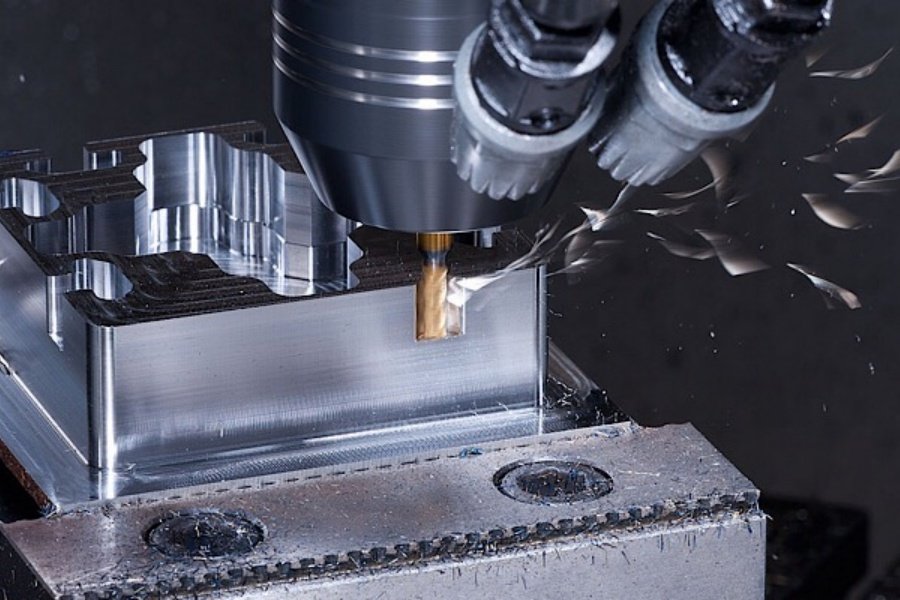
In high-precision manufacturing, face milling is one of the most frequent yet critical operations. When configuring a heavy-duty CNC milling machine, milling parameters directly dictate production throughput, workpiece surface integrity, and overall tool life. Selecting sub-optimal variables often leads to structural vibration, premature tool chipping, or severe part warping. This industrial guide provides a deep-dive analysis into scientifically selecting and calibrating face milling process parameters for flawless execution. To see how these optimized parameters are applied in real-world manufacturing, explore our core CNC milling machine processes designed for high-tolerance components.
1. Speed & Feed Kinetics
1.1 Cutting Speed (Vc)
Cutting speed is predominantly governed by the metallurgical properties of the workpiece, the tool substrate, and the specific cutter geometry.
Steel Components : Typically maintained within a baseline range of 100 – 200 m/min.
Tool Material Factor: High-Speed Steel (HSS) cutters are strictly limited to the lower velocity boundaries due to thermal thresholds, whereas Cemented Carbide and Ceramic inserts allow for elevated cutting speeds.
1.2 Feed Rate Optimization (Vf & fz)
The feed velocity must be balanced against the depth of cut, width of cut, and the structural rigidity of the setup. In precision machining, table feed rate (Vf) is calculated using the industrial formula: Vf = n × z × fz (where n is spindle speed, z is the number of cutter teeth, and fz is feed per tooth).
Milling Aluminum: Feed per tooth (fz) typically ranges from 0.2 – 0.4 mm/tooth.
Milling Steel: Feed per tooth (fz) is restricted to 0.1 – 0.2 mm/tooth to mitigate heavy shock loading.
2. Axial & Radial Engagement Limits
2.1 Axial Depth of Cut (ap)
Axial depth should be determined by the total machining allowance rather than raw part thickness. To prevent severe mechanical stress and vibration:
Rough Milling: Allocate a larger ap (typically 1.5 – 4.0 mm) to remove up to 80% of excess material efficiently.
Finish Milling: Restrict ap to a minute margin (typically 0.1 – 0.5 mm) to achieve ultra-tight dimensional tolerances and minimize tool deflection.
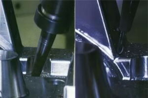
2.2 Radial Width of Cut (ae)
In standard plane engagements, the radial width of cut (ae) should generally be controlled within 60% to 75% of the cutter diameter (D).
This geometric configuration prevents the tool center line from aligning identically with the workpiece edge, ensuring a smooth entry profile, reducing entry shock, and protecting the insert corners from premature micro-chipping.
3. Tool Selection Matrix & Fluid Dynamics
3.1 Advanced Tooling Metallurgy
High-Speed Steel (HSS): Reserved for complex, specialty profile cutters requiring maximum structural toughness and fracture resistance.
Cemented Carbide / Indexable Inserts: The absolute industry standard for high-hardness matrices (such as cast iron, titanium, and duplex alloys) and high-efficiency flat surface production. Face Mills with larger diameters are utilized for expansive surfaces, while Three-Sided Edge Mills are optimized for precision step contours. Leveraging these high-performance tooling setups requires robust machinery. Check out our factory-direct precis/cnc-milling/ion CNC milling services to view our full workshop capabilities and part portfolios.
3.2 Cutting Fluid Applications
Thermal Management (Cooling): When machining gummy, high-temperature alloys like austenitic stainless steel, high-pressure, high-volume flood or mist cooling is mandatory to prevent material adhesion.
Tribological Management (Lubrication): For aluminum alloys, cutting fluids formulated with premium oiliness and extreme-pressure (EP) lubricants are necessary to eliminate micro-welding on the insert rake faces.
4. Mathematical Calibration & Empirical Validation
4.1 Spindle Speed Formula (n)
The spindle speed (n, in rpm) is mathematically tied to the desired cutting speed (Vc) and the exact cutting tool diameter (D, in mm) via the baseline mechanical formula:
n = (1000 × Vc) / (π × D)
For example, utilizing a 20mm diameter cemented carbide face mill running at a target cutting speed of 200 m/min, the required spindle rotation calibrates directly to approximately 3180 rpm.
4.2 Empirical Machining Trials
Initial parameter sets are baseline estimates. True optimization requires real-world trial runs on the shop floor. Operators must execute a narrow-scope test cut to carefully monitor:
· Flank & Rake Wear Rates:Check for micro-chipping or premature edge degradation under magnification.
· Surface Roughness (Ra):Verify that the micro-inch or micrometer target finish is met without tearing.
· Harmonic Vibration (Chatter):Audit the machine spindle sound to dynamically fine-tune the feed velocity or speed parameters, ensuring a perfectly stable cutting window.
Conclusion
Achieving flawless execution in CNC milling machine milling processes requires a rigorous synthesis of empirical metal-cutting math and field-tested manufacturing experience. At XML Tech, backed by over 10 years of cross-industry CNC hardware machining mastery and nearly two decades dedicated to high-precision component production, we run standardized DFM protocols for every production lot. From optimizing tool kinematics to programming custom multiaxial paths, our engineering team ensures your components achieve maximum dimensional accuracy and superior surface integrity.
eady to optimize your next project? Get a fast quote through our [CNC Milling Machine Processes and Structures] page today!