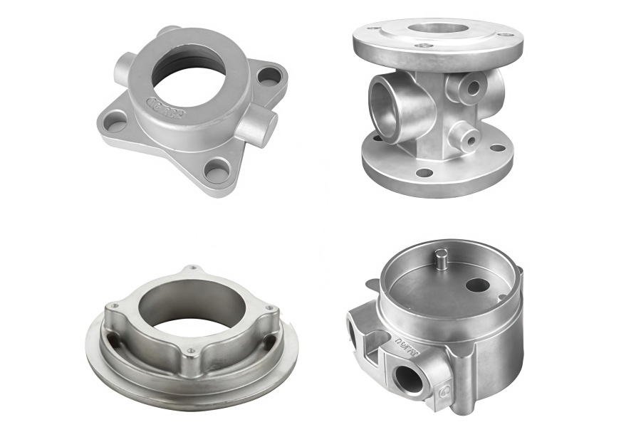
A die casting tool is ordered once. After the steel is cut, every angle on the part is fixed, and the only way to change one is to weld, re-machine or scrap the die. That is why draft belongs in the design review, not in a note after the first sample.
Two numbers on the print carry most of that risk: die casting draft angle and wall thickness. Draft angle controls whether the casting releases. Wall thickness controls whether it fills and whether it stays straight as it cools.
This article covers what draft does inside the die, the values that hold for aluminum, zinc and magnesium work, and how both numbers reach the tooling quote.
What Draft Angle Actually Does Inside the Die
A draft angle is the taper built into every surface that runs parallel to the direction the die opens. Without it, the casting shrinks onto the core and the die has to drag the part off.
The angle is not a finishing allowance. It is the clearance that lets metal leave steel.
Release, Ejection and Surface Drag
Three things happen at ejection, and draft angle affects all three. The casting shrinks as it cools, so it grips the core. The ejector pins then push against a part that is still holding on. And the surface slides across the die wall on its way out.
A shallow angle loads all three at once. Ejection force rises, ejector pin marks appear on the part, and the sliding contact scuffs the as-cast skin. On a textured face the scuffing gets worse, because the texture gives the metal somewhere to key into.
Why the Angle Is a Tooling Decision, Not a Finishing One
You cannot polish your way out of a missing draft. Polishing changes the surface, not the taper. A die with too little draft keeps dragging until the cavity is re-cut, and re-cutting removes the very finish the customer specified.
That is the reason the number belongs on the drawing before the tool is ordered. Once the cavity has been spark-eroded and textured, adding a degree means rebuilding steel that is already heat treated.
The aluminum, zinc and magnesium work on our Die Casting Services page all starts from the same rule: the draft is quoted from the print, and the print is what the die follows.
Die Casting Draft Angle Values by Surface: Walls, Cores and Textures
Published values for aluminum sit in a narrow band. Kinetic Die Casting, a California die caster, lists 1° to 3° as the minimum draft range for aluminum and describes a draft angle per side of two degrees as typical for production parts.
One number across the whole part is usually wrong, because exterior walls and interior cores do not behave the same way. A die casting draft angle chart shows the range, not the answer.
Exterior Walls and Interior Cores Are Not Symmetric
An exterior wall shrinks away from the cavity as the casting cools, so that movement helps it release. An interior core is surrounded by metal, so the casting shrinks onto it and grips harder.
The practical consequence is that interior surfaces need the larger end of the published range. That is the working minimum draft angle to plan around: two degrees for exterior walls in aluminum, and the upper end of the range for cored walls, deep pockets and any cored hole. A cored hole draft angle has to clear the full depth of the pin, so it takes the steepest callout on the print.
Depth matters as much as the angle, and this is where designers misread the tables. A two-degree taper over a 10 mm wall clears by about 0.35 mm per side. The same two degrees over a 50 mm wall clears by about 1.75 mm. A deep feature releases more easily than a shallow one at the same angle, so the features that fail are usually short and steep rather than tall.
Draft Angle for Textured Surfaces, and Why Zinc Differs
Texture adds draft requirement above the base angle, because every peak of the texture is a small undercut the casting has to slide past.
Published mold texture guidance sets the draft angle for textured surface work at 1.5° per 0.001 in (0.025 mm) of texture depth. That figure comes from injection molding practice, and die casters apply the same logic because the release problem is identical. On a casting carrying a 0.05 mm texture, the addition alone is three degrees before the base angle is counted.
The zinc die casting draft angle runs the other way. Kinetic notes that zinc parts require less draft than aluminum because the metal is more malleable and does not grip the die as hard. When the alloy changes late in a program, treating the aluminum range as the conservative default is the safer call.
Wall Thickness: Where Uniformity Matters More Than the Number
Wall thickness is a range rather than a single value, and the published minimums are lower than most designers expect.
Kinetic lists 0.060 in (1.5 mm) as the normal minimum section for small aluminum parts and 0.090 in (2.3 mm) for medium parts. Those figures are floors, not targets. A die casting wall thickness at the floor fills only when the gate and the machine are set up for it.
Thick Sections, Shrinkage and Internal Porosity
The problem with a thick section is not the thickness. It is the transition around it.
A thick section cools last, so it stays liquid while the thin sections beside it have already frozen. Metal has to feed into that liquid pocket as it shrinks, and once the gate has solidified the pocket pulls a void instead. That void is die casting porosity, and it sits under the surface where a later machining cut will open it.
This is why a uniform wall casts more reliably than a light part with one heavy boss. The boss is where the porosity lands, and the boss is usually the mounting point that gets drilled and tapped.
Thin Walls and Fill Pressure
A thin wall is not free either. Metal has to reach the far end of the cavity before it freezes, so thin sections push the process toward higher fill velocity and higher pressure. Both raise tool wear and narrow the process window.
Thin walls also magnify any draft problem, because a wall that deflects during ejection has less material to resist it. Where a design needs thin walls for weight, the draft angle and the ejection layout have to carry more of the release job.
The usual practice is to keep the main wall in the middle of the range the caster can hold, and treat every thin section as a feature that needs its own gate review. Alloy choice shifts that range, which is why aluminum die casting work is reviewed by alloy rather than by wall number alone.
Corners, Ribs and Bosses: The Features That Fight the Draft
Corners, ribs and bosses are where draft quietly disappears. A designer can set the wall angle correctly and still produce a part that will not release, because one of these features was drawn square.
The die casting design rules that matter most are not the ones about the main wall. They are the ones about the small features attached to it.
Fillet Radii and Stress Concentration
An inside corner without a fillet radius is a filling problem and a stress riser at the same time. Metal flows slowly past a sharp internal corner, so the corner fills last and often fills incompletely. The same corner concentrates cooling stress, which is how a casting cracks at a corner during ejection rather than in service.
Fillets fix both, and a generous internal fillet is cheaper than a sharp corner because it removes a polishing step on the die. Ribs follow the same rule at their roots. A rib meeting a wall at a sharp angle creates a thick section at the junction, which is exactly the porosity site described earlier.
Bosses are the third offender. A boss is a thick cylinder standing inside a thin wall, and the wall around it has to taper in both directions. Bosses drawn with vertical sides cannot be cast without a slide or a hand-loaded insert, and either one changes the tooling quote.
Machining Allowance: What to Leave for Secondary CNC Work
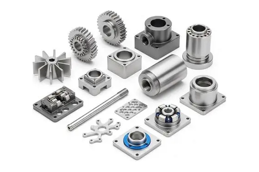
Most die castings are not shipped as cast. Bearing bores, sealing faces and mounting pads get machined, so the drawing has to state how much metal to leave and where.
Machining allowance is specified per surface, not as one number for the whole casting. A face that will be milled flat needs enough stock to clean up a warped casting. A face that stays as cast needs none, and adding stock there only adds weight and cutting time. The scope sits alongside our CNC Machining Services, because the allowance decision is made by the shop that will take the cut.
Datum Selection on a Cast Surface
A cast surface is a poor datum. It carries draft, it carries parting line mismatch, and its tolerance is wider than any machined feature. When a program zeroes on an as-cast face, every machined feature inherits that variation.
The better approach is to datum on the first machined surface and work from it. That costs one extra operation up front and removes a stack-up that would otherwise have to be absorbed somewhere else.
Published aluminum die casting tolerance values run to ±0.002 in per inch, with an additional ±0.001 in to ±0.015 in across the parting line depending on size. A machined feature that has to hold tighter than the machine tolerance table allows needs its own operation, and that is a cost decision rather than a casting decision.
For how secondary operations move the unit price, the breakdown of the six quoted cost drivers covers where the money actually goes.
How Draft and Wall Thickness Show Up in the Tooling Quote
Die casting tooling cost is where draft and wall thickness stop being a design detail and become a number on a purchase order.
Every feature that cannot release in the line of draw needs a slide, a lifter or a separate core. Each one adds steel, adds a mechanism that can fail, and adds maintenance across the life of the tool. A part with four slides is more than four times the tool of a part with one, because the die base and the tryout grow with them.
Wall thickness moves the quote from the other direction. A thin wall needs higher fill pressure, which pushes the machine toward larger tonnage and more expensive die steel. A thick wall needs longer cycle time, because the casting has to stay in the die until it is stiff enough to eject without warping.
Neither cost can be negotiated away after the die is cut. Both are set by the drawing, which is why a design review before tooling is the only place these two numbers can still be changed for free.
Conclusion
Die casting draft angle and wall thickness are cheap to change on a screen and expensive to change in steel. Set the draft per surface rather than per part, keep the wall uniform and inside the range the caster can fill, fillet the corners that would otherwise need a slide, and specify machining allowance face by face.
If you have a casting drawing under review, send it over with the model through the CNC Machining Quote Form. We will mark the features that will not release and the sections that will pull porosity before the tool is quoted. Our Die Casting Services page lists the aluminum, zinc and magnesium work we run, and the About Us page covers how the shop is set up. Other design and cost breakdowns are collected on the Blog Homepage.
Sources
Fictiv. “Injection Molding Design Guide.” Fictiv, www.fictiv.com. Accessed 6 Nov. 2026.
Kinetic Die Casting Company. “Draft Angle Requirements on Aluminum Die Casting Box Parts.” Kinetic Die Casting, www.kineticdiecasting.com/draft.html. Accessed 6 Nov. 2026.
Kinetic Die Casting Company. “Technical Information about Die Castings.” Kinetic Die Casting, www.kineticdiecasting.com/tech.html. Accessed 6 Nov. 2026.
Kinetic Die Casting Company. “Zinc Die Casting Parts Company.” Kinetic Die Casting, www.kineticdiecasting.com/zinc.html. Accessed 6 Nov. 2026.