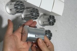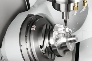
In high-density electronic designs—such as smart wearables, TWS earbuds, semiconductor test sockets, medical instruments, and industrial docking stations—traditional plug-in connectors struggle to meet strict spatial limitations and high lifecycle demands. Pogo pins (spring-loaded connectors) provide superior durability, dynamic shock absorption, blind-mating tolerance, and exceptionally low contact resistance.
However, achieving millions of stable compressions and milliohm-level electrical performance requires uncompromising standards in Swiss-type CNC micro-machining, metallurgy, electroplating, and spring engineering. This guide breaks down the structural mechanics, current-routing architectures, critical selection parameters, and manufacturing standards required to produce high-reliability pogo pins.
1. Mechanical Anatomy & Material Engineering
A standard pogo pin consists of three core components: the Plunger, the Barrel, and the Internal Spring. In high-frequency or heavy-current applications, specialized elements like conductive micro-balls or internal diverters are incorporated.
Component Materials & Selection Criteria
The selection of base metals and insulating materials directly dictates mechanical longevity, electrical conductivity, and thermal stability:
| Component | Common Materials | Key Properties & Selection Criteria |
| Plunger | C3604 Brass, C17200 Beryllium Copper, Tellurium Copper | High electrical conductivity and excellent machinability. Beryllium copper provides superior yield strength to prevent tip deformation under repeated impact. |
| Barrel | C3604 Brass, Copper Alloys | Precision Swiss-type turned with internal bore roughness strictly controlled to Ra < 0.2 µm to minimize sliding friction and plating wear. |
| Spring | SUS304/316 Stainless Steel, Music Wire (SWP), Beryllium Copper | High fatigue resistance and creep resistance to maintain consistent spring force (k-factor) over extended compression cycles. |
| Insulating Housing | Engineering Plastics: PEEK, POM, LCP, PTFE | Outstanding dielectric strength, low moisture absorption, and dimensional stability to withstand SMT reflow soldering and mechanical stress. |
Surface Electroplating Specifications
To lower contact resistance, prevent oxidation, and resist galvanic corrosion, components undergo precise multi-layer electroplating:
Nickel Undercoat (1.5–3.0 µm): Serves as a diffusion barrier preventing copper migration while providing a hard structural base.
Gold Topcoat (Au 3u”–50u” / 0.075–1.25 µm): Delivers superior electrical conductivity and chemical inertness. Cobalt-hardened gold is applied for high-frequency mating applications to extend wear life.
Intermediate/Functional Layers (e.g., Pd-Ni Alloy): Employed in multi-layer plating schemes for extreme durability or harsh corrosive environments.
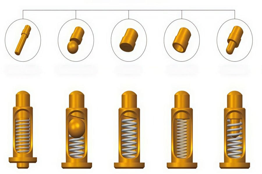
High-Current & Signal Stability: 4 Internal Diverter Designs
A primary failure mode in standard pogo pins is current passing directly through the internal stainless steel spring. Because steel has significantly higher electrical resistance than copper alloys, heavy currents cause inductive heating, spring annealing, loss of elasticity, and eventual connector burn-out.
To force current to travel directly from the plunger to the barrel, four primary internal architectures are engineered:
Bevel Cut Structure (Bias Cut)
The plunger base is machined at an angle (typically 4° to 9°). Under compression, the spring exerts a lateral vector force that pushes the plunger base firmly against the inner barrel wall. This establishes a direct low-resistance contact path, bypassing the spring.
Ball-Embedded Structure (Steel/Ruby Ball)
A precision micro-ball is seated between the plunger base and the spring. Under compression, the ball forces 360° contact between the plunger and barrel, holding dynamic contact resistance below 15 mΩ for high-speed signal integrity.
Back-Drilled Structure
The plunger base is hollowed out to seat a portion of the spring inside the plunger body. This maximizes spring travel within a minimal total barrel height, ideal for ultra-low-profile board-to-board applications.
Split-Plunger / High-Current Structure
Incorporating internal conductive cones or dual-piece plungers distributes heavy current loads, safely transmitting 5A to 50A+ continuously without thermal degradation.
3. Pogo Pin Mounting Forms & Packaging Types
Depending on board layouts, enclosure sealing, and automated assembly requirements, pogo pin connectors are manufactured in several structural variations:
| Mounting Type | Structural Features | Primary Applications |
| SMT / SMD (Surface Mount) | Flat-bottom barrel or positioning pegs; compatible with pick-and-place automation and reflow soldering. | Smartphones, TWS earbud charging cases, board-to-board interconnects |
| Through-Hole (DIP) | Features a solder tail extending through PCB vias for wave or manual soldering. | Industrial controllers, high-vibration systems, test fixtures |
| Double-Ended (Floating) | Plungers at both ends; seated directly in insulating housings without soldering. | Modular test sockets, solderless flexible PCB interconnects |
| Right-Angle / Side-Mount | Tail pins bent at 90° for edge-board connections or side docking. | Device side ports, horizontal sliding charging docks |
| Magnetic Assembly | Pogo pin arrays combined with N52 Neodymium magnets in CNC or overmolded housings. | Medical quick-connects, rugged outdoor power interfaces |
4. Key Engineering Selection Parameters
When specifying custom pogo pins or multi-pin block assemblies, hardware engineers must evaluate the following performance parameters:
Working Stroke vs. Max Stroke
Operate pogo pins within their recommended working stroke (typically 60%–70% of total travel). Over-compression risks damaging PCB pads, while under-compression leads to intermittent contact.
Spring Force Profile
Pre-load Force: Initial retention force holding the plunger in place at rest to resist false triggers under mild vibration.
Working Force: Calibrated between 30g and 150g to break through surface oxidation without puncturing gold plating on mating pads.
Contact Resistance & Dynamic Impedance
Static contact resistance should remain < 30 mΩ, with dynamic resistance fluctuations held under < 10 mΩ during high-vibration scenarios.
Mechanical Life
Standard consumer electronics require 10,000 cycles, whereas semiconductor test sockets and industrial interfaces demand 100,000 to 1,000,000+ cycles.
5. Precision CNC Manufacturing & Quality Control Protocols
As a source manufacturer specializing in precision hardware components, we focus exclusively on custom, ultra-precise metallic and non-metallic parts rather than complete consumer end-devices.
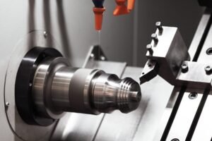
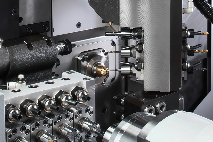
Swiss-Type CNC Micro-Turning
Tight Tolerance Control: Multi-axis Swiss-type CNC lathes machine barrels and plungers from solid bar stock with tolerances controlled strictly within ±0.005mm to ±0.01mm.
Bore Surface Finish: Special micro-reaming techniques achieve an internal bore finish of Ra < 0.2 µm, drastically reducing mechanical wear on plunger plating over extended compression cycles
Comprehensive Material Capabilities
Conductive & Structural Metals: Free-cutting brass, Tellurium Copper, Beryllium Copper, Stainless Steel (304/316L), Titanium alloys, and high-strength Aluminum alloys.
Engineering Plastic Housings: Precision multi-axis milling of engineering plastics (PEEK, POM/Delrin, LCP, PTFE) for custom insulator blocks, test sockets, and multi-pin housings.
Rigorous Quality Assurance Protocols
Optical Dimension Verification: High-magnification Optical Measurement Systems and Keyence Image Measurement Systems verify micro-bores, bevel angles, and tip geometries.
Plating Inspection (XRF): X-ray Fluorescence gauges monitor nickel and gold plating thickness to ensure uniform corrosion resistance and conductivity.
Dynamic Force-Displacement Profiling: Automated testing equipment records real-time force, stroke, and dynamic contact resistance curves.
Environmental & Fatigue Testing: Neutral Salt Spray (NSS) corrosion testing paired with automated multi-station compression testers verifying cycle life capabilities up to 1,000,000 compressions.
6. Frequently Asked Questions (Engineering FAQ)
Q1: How do you prevent spring overheating during heavy current transmission (>5A)?
A1: We incorporate a bevel-cut plunger or ball-embedded structure that forces the plunger base firmly against the brass barrel wall. This creates a primary low-resistance pathway (< 10 mΩ) that bypasses the steel spring completely, preventing resistive heating and thermal annealing.
Q2: What causes dynamic impedance instability, and how is it mitigated?
A2: Dynamic impedance spikes are primarily caused by internal barrel burrs, poor lateral contact during vibration, or plating wear. We eliminate these issues by maintaining an internal barrel surface finish of Ra < 0.2 µm via micro-honing, utilizing precision bias-cut plungers, and applying hard gold plating over a dense nickel barrier.
Q3: Can you manufacture custom insulating housings alongside pogo pins?
A3: Yes. As an all-around hardware component manufacturer, we machine both high-precision metallic pins and custom insulating blocks made from engineering plastics such as PEEK, POM, LCP, and PTFE, supplying fully matched pin-and-housing hardware sets.
Q4: Why is stress relief (such as T651 temper) important when machining surrounding fixtures?
A4: When machining multi-pin test plates or housings, internal residual stress in raw stock can cause warping after deep CNC pocketing. Utilizing stress-relieved materials (such as T651 aluminum or annealed plastics) prevents post-machining deformation, ensuring micro-drilled mounting holes retain precise center-to-center pitch tolerances (down to ±0.01mm).
Partner with a Precision Hardware Source Manufacturer
Whether you are developing next-generation medical wearables, high-frequency semiconductor test sockets, or rugged industrial charging docks, connector reliability starts at the component level.
Contact our technical team today to submit your CAD drawings (STEP/DWG) for a comprehensive DFM (Design for Manufacturability) evaluation, custom material selection, and precision machining quotation.