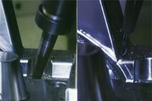
When designing custom mechanical components for consumer hardware, mold inserts or precision instruments, selecting the right machining tolerance is one of the most critical decisions for your project. Many product teams spend hours reviewing machine datasheets, yet overlook how fixturing, material behavior and machining strategy change the final part accuracy. This guide breaks down the real, repeatable precision you can expect from 5-axis CNC machining, rather than theoretical lab values. We will walk through material-specific tolerance ranges, key influencing factors, common drawing mistakes, and how to decide whether multi-axis machining is truly necessary for your design. Whether you are quoting a prototype or preparing for low-volume production, this article helps you set realistic tolerance requirements and avoid unnecessary manufacturing costs.
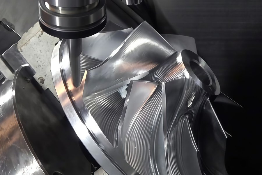
A Common Misconception: Machine Spec Does Not Equal Final Part Precision
Many product engineers and hardware buyers begin their sourcing journey with one central question: how precise can custom five-axis CNC machining get for my component? A pervasive misunderstanding in the product development world is that the positioning accuracy printed on a machine brochure directly translates to the tolerance you can hold on finished machined parts. This flawed assumption often leads to over-ambitious drawing specifications, inflated manufacturing costs, and unexpected delays during prototype and small batch production.
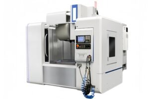
The inherent accuracy of a multi-axis machine is only the hardware foundation. The final dimensional and geometric precision of your finished component is a combined result of many interconnected factors: machine rigidity, custom fixture design, CAM toolpath programming, raw material thermal behavior, cutting parameter selection, and post-process quality inspection. Even a high-grade machining center will struggle to maintain tight geometric tolerances if the workpiece is clamped improperly, or if toolpaths cause unwanted vibration during material removal.
Designers who mostly work with conventional milling often underestimate the impact of repeated re-fixturing. When machining multi-sided features on standard milling equipment, the part must be unclamped, re-aligned and re-secured multiple times to access all faces. Every time you reposition the workpiece, minor alignment drift occurs. After two, three or four separate setups, these tiny errors stack up. This cumulative shift makes position tolerance and concentricity extremely difficult to control, especially for parts with angled holes and compound curved surfaces.
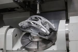
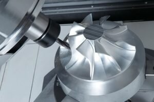
The primary benefit of five-axis machining is the ability to complete most or all features in a single setup. By keeping the workpiece fixed to one reference datum throughout the full machining cycle, we eliminate the stack-up error created by multiple re-clamping operations. This capability makes the process ideal for components with freeform curves, undercut geometry and holes drilled at compound angles. That does not mean five-axis machining is always the best choice for every custom part. Simple flat geometry with all features on one plane can be produced more economically on standard milling equipment, without paying the premium for multi-axis processing.
Two primary five-axis workflows exist, and it is critical to understand the difference when planning your project: continuous five-axis machining and positional 3+2 machining. In 3+2 positional work, rotary axes tilt the workpiece to a fixed angle and lock into place; cutting then happens with linear axes only. This method works well for angled holes and inclined flat planes, and carries lower machine hour costs. Continuous five-axis machining keeps rotary axes moving synchronously as cutting proceeds, which is required for smooth, organic freeform contours. Each method has its own precision limits and cost profile, which our engineering team reviews during every cnc machining dfm analysis for curved parts we perform for clients.
Realistic Tolerance Ranges By Material for Custom Five-Axis Machined Parts
The tolerance values listed below represent stable, repeatable results for prototype and low-volume custom manufacturing. These are real-world production figures, not theoretical lab limits measured under perfect temperature-controlled test environments. All examples apply to consumer hardware, mold inserts, and precision instrument components.
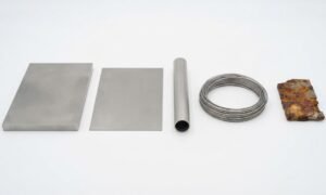
- Aluminum Alloys (6061, 7075) Standard dimensional tolerance: ±0.025 mm. Critical mating features can consistently hold ±0.01 mm. Aluminum has a relatively high thermal expansion coefficient. Thin wall aluminum structures deform easily under cutting heat and clamping pressure. A well-designed custom fixture controls clamping force carefully to avoid squeezing distortion. For angled holes and compound curved surfaces, position tolerance can normally be maintained within ±0.02 mm. This makes aluminum the most popular material for tight tolerance cnc machining for aluminum projects across consumer product development.
- Stainless Steel (304, 316L) Standard tolerance: ±0.03 mm. Selected critical assembly features can reach ±0.015 mm. Stainless steel develops work hardening during cutting, which accelerates tool wear and extends machining cycle time. When drawings specify tight tolerances, we reduce cutting depth and lower feed rates, paired with increased coordinate measuring machine sampling during quality checks. Stainless steel parts demand more conservative cutting strategies to avoid surface tearing and dimensional drift.
- Mold Steels (P20, H13) Standard tolerance: ±0.03 mm. Contour tolerance on complex mold cavities can stay within ±0.02 mm. This is the main reason mold makers choose multi-axis milling for custom mold insert cnc machining tolerance requirements. Smooth milled surfaces reduce the hours of manual hand polishing required for mold inserts, shortening lead times and lowering total mold fabrication cost.
- Engineering Plastics (POM, PEEK) Plastics deform readily under heat generated during cutting, so metal tolerance standards cannot be copied directly onto plastic drawings. Standard tolerance ±0.05 mm. For thick, short structural features, ±0.025 mm is achievable. We strongly recommend DFM adjustments for plastic components, because overly tight tolerances on plastic machined parts lead to high reject rates. This is a common pitfall for teams designing custom machined plastic components tolerance requirements for prototype testing.
Surface Roughness Reference: Standard milled finish: Ra 1.6 ~ 3.2 μm. Optimized streamline toolpaths can deliver Ra 0.4 ~0.8 μm without secondary polishing, perfect for exposed cosmetic curved surfaces on consumer-grade hardware. This is a key consideration for teams working on cnc machining surface roughness for cosmetic parts.
A vital rule for designers: ultra-tight tolerances should only be applied to critical mating assembly features. Applying extreme tolerance requirements to every single dimension on your drawing will unnecessarily increase machining cost and extend lead times. Our engineers separate critical functional dimensions from non-critical cosmetic dimensions in the drawing review phase, to balance performance, quality and budget.
Five Key Factors That Determine Precision of Multi-Axis CNC Machining
1. Custom Fixture Design & Workholding Strategy
Many buyers focus their full attention on machine capability, and overlook the huge impact of fixturing on final part tolerance. In multi-axis milling, fixture design is one of the largest variables affecting finished component quality. Standard vises used for basic milling often collide with the spindle during rotary workpiece movement. Poor fixture design creates two major risks: over-clamping force that squeezes and warps thin workpieces, or fixture interference that forces the switch to 3+2 positional machining, sacrificing precision and efficiency.
When reviewing your 3D STEP model, our team will examine part geometry in advance to design purpose-built workholding. The core goal is to keep the workpiece datum stable throughout rotary movement while minimizing clamping stress, to avoid deformation of thin walls or delicate features. Vacuum chucks and low-stress custom fixtures are commonly used for thin-walled components in our small batch cnc machined components production.
2. Machining Strategy: Continuous Multi-Axis vs 3+2 Positioning
It is common for customers to confuse continuous multi-axis machining and 3+2 positional machining. The two methods differ greatly in achievable precision, cycle time and total manufacturing cost. 3+2 positioning locks rotary axes after tilting the workpiece, then cutting uses only linear axes. It works well for angled holes and inclined flat planes, and delivers excellent value for many projects. It costs less than full continuous multi-axis processing.
Continuous multi-axis machining synchronizes rotary workpiece movement during cutting. This process is built for complex freeform surfaces and deep undercuts. It demands advanced CAM programming, high-performance cutting tools and rigid machine construction. It delivers superior contour accuracy for organic curved profiles, but machine hour rates are higher.
During our DFM assessment, we recommend the most suitable strategy for each project. In many cases, 3+2 positioning meets all drawing tolerance requirements and saves you significant manufacturing expense. We never recommend continuous multi-axis processing if a simpler milling workflow can fulfill your specifications. Our goal is to deliver precision cnc machining for consumer hardware at the lowest practical cost, without over-engineering your parts.
3. Raw Material Properties and Part Geometry
Thin walls and slender structures create the biggest precision challenges for custom machined components. Even high-grade milling equipment cannot fully eliminate deflection caused by cutting force and heat. For aluminum parts, walls thinner than 0.8 mm and stainless steel walls thinner than 1.2 mm will reduce dimensional stability. This is a major topic in cnc machining thin wall aluminum parts DFM consultations.
Our engineers identify these high-risk features during drawing review. We propose design changes such as adding internal radii or adjusting wall thickness, preserving product function while making the component easier to machine reliably and reducing scrap risk. Small adjustments in your CAD file can drastically improve tolerance consistency and lower your prototype cost.
4. Cutting Tools, Tool Overhang and Vibration Chatter
When working at tilted angles in multi-axis machining, tool overhang length changes constantly as the workpiece rotates. This easily creates cutting chatter. Chatter leaves visible wave-like tool marks on the part surface and causes dimensional and contour tolerance failure. Our process engineers select short, rigid solid carbide cutters, adjust spindle speed and feed rates, and control chip load to reduce vibration. This is one of the subtle differences between basic programming and professional custom machining services.
5. Inspection and Quality Verification
Precision is not guaranteed simply by running a part through a milling machine. For components with tight tolerance requirements, we deploy coordinate measuring machines for inspection, focusing on geometric tolerances like position and profile, not only simple linear dimensions measured with handheld calipers. Full inspection reports can be supplied with shipments for customer incoming quality control checks. This rigorous inspection process is essential for validating cnc machining geometric tolerance guide compliance for your drawing.
Precision Comparison: Standard Milling vs Multi-Axis Machining
Many hardware buyers want to understand the practical precision gap between conventional milling and multi-axis machining for their custom components.
Standard milling equipment can only machine features facing upward. Multi-sided geometry must use multiple re-clamping operations. Accuracy on a single plane is excellent, but cross-plane position tolerance suffers from accumulated alignment shift. This workflow is best suited for simple plates and box-style components, and it struggles with undercuts or compound curved surfaces.
Multi-axis machining allows full access to multiple faces of the workpiece in one clamping operation. It removes the cumulative alignment error of repeated re-fixturing. Cross-plane position and contour accuracy far exceed what you can achieve with repeated setups on standard milling machines. For parts with angled holes, compound curves and undercuts, multi-axis machining is the most reliable way to hold drawing tolerances.
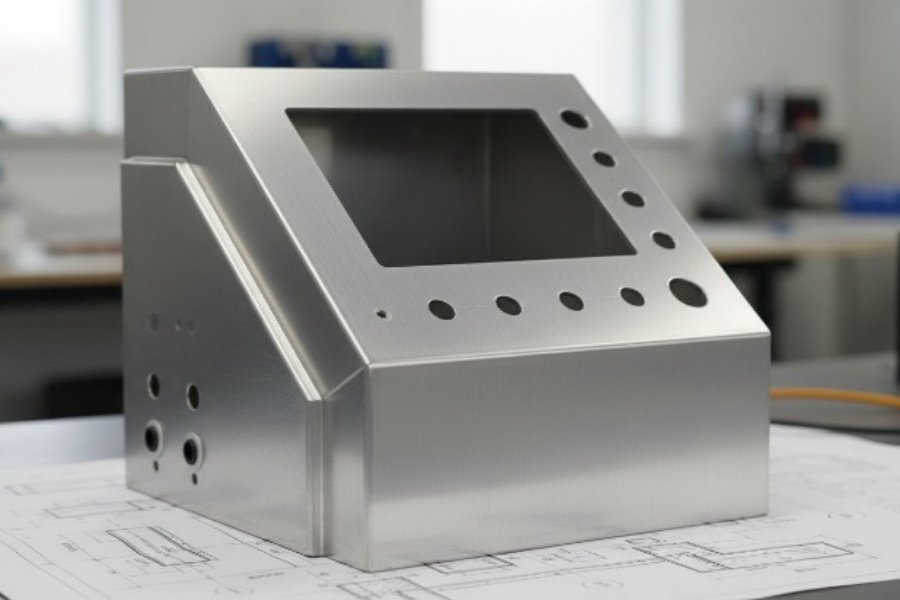
Take a real example: an aluminum housing with multiple angled mounting holes. Machined on standard milling equipment, four separate clamping operations are required, and cross-hole position tolerance can only reliably hit ±0.08 mm. Using multi-axis machining in a single setup, the same feature maintains position tolerance within ±0.02 mm. This also cuts fixture cost and shortens lead time. This example is one of the most common use cases we see for cnc machining angled hole position tolerance requests.
However, an important caveat: if all your features sit on a single flat plane, standard milling is completely sufficient. Switching to multi-axis machining in this case adds cost with zero improvement in precision. Our team will be transparent and recommend the most economical process for your component.
Common Tolerance Specification Mistakes Engineers Make On CNC Drawings
When customers submit STEP files for quotation, we repeatedly see the same tolerance specification mistakes that drive up cost and create production risk.
- Applying ultra-tight tolerance to every dimension on the drawing. Non-critical cosmetic dimensions do not need ±0.01 mm tolerance, and this unnecessary requirement greatly increases the price of your machined parts. Only apply tight tolerances on mating assembly surfaces.
- Confusing linear dimensional tolerance with geometric tolerances. Profile and position are the critical values for multi-axis machining work, more important than simple size measurements. This is a core lesson from our cnc machining geometric tolerance guide.
- Using metal tolerance standards for plastic parts. Thermal deformation in PEEK or POM will cause high scrap rates if you copy aluminum tolerance values directly onto plastic drawings.
- Specifying lab-grade theoretical machine tolerance for volume production. The theoretical limit of a machining center is not realistic for consistent batch manufacturing.
We offer free DFM analysis for all incoming projects. Send over your STEP or IGES drawing, our engineers will review tolerance feasibility, flag high-risk features, and recommend whether standard milling, 3+2 or full continuous multi-axis machining is best suited. This is our standard process for custom cnc machining prototype tolerance reviews.
FAQ for Multi-Axis CNC Machining Precision
Q1: What is the theoretical maximum precision achievable on multi-axis milling equipment?
High-end machining centers can achieve ±0.005 mm on tiny features under ideal constant-temperature lab conditions. This theoretical limit is not practical for regular batch or prototype manufacturing. The associated cost is extremely high, and nearly all consumer hardware and mold projects do not require this level of precision.
Q2: What is the smallest feature multi-axis milling can produce?
Typically, we can machine small slots and holes down to 0.3 mm. Tolerance for micro features is limited by tool rigidity. Thinner cutting tools deflect more easily, so tolerance must be relaxed appropriately for micro details. This is a frequent topic in prototype cnc machining tolerance limits consultations.
Q3: Does custom fixture design affect machining precision?
Absolutely. Fixtures must avoid rotary collision while distributing clamping force evenly. For thin-wall workpieces, vacuum fixtures or low-stress custom fixturing is preferred to eliminate clamping deformation. Good cnc machining fixture design for complex parts directly improves yield and tolerance consistency.
Q4: How much more expensive are tight tolerance custom machined components?
Tighter tolerances demand reduced cutting speed, extra inspection steps and smaller batch sizes per setup. Cost can rise from 20% to 80% as tolerance tightens, based on part complexity. Our DFM review helps balance part performance and manufacturing budget.
How to Tell If Your Part Is Suitable for 5-Axis CNC Machining
You can quickly self-evaluate your design against three criteria:
- The part includes two or more machining planes at different angles, angled holes or undercut geometry;
- Your drawing enforces strict position or profile geometric tolerances across multiple faces;
- This is a new product prototype or small batch run, and you want to avoid building multiple complex fixtures for repeated re-clamping.
If you meet these criteria, multi-axis machining will deliver stable precision and reduce scrap risk caused by multiple re-clamping. If your geometry is simple with all features on one plane, standard milling will be the more budget-friendly selection for your low volume custom cnc manufacturing project.
Conclusion: Focus On Consistent Part Tolerance, Not Machine Datasheet Specs
When you select a CNC manufacturing partner, avoid judging capability only from the datasheet parameters of their milling equipment. The real factor controlling yield of your custom machined parts is the complete manufacturing system: process planning, custom fixture design, inspection workflow, and material deformation management.
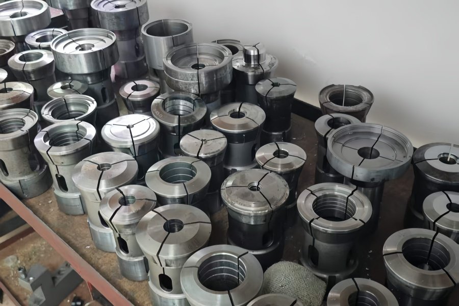
The core value of multi-axis CNC machining is removing alignment error from repeated re-fixturing. It delivers stable tolerance for parts with curved surfaces, angled holes and undercuts, but multi-axis machining is not a universal solution for every CNC project. Our team provides full custom machining services, supporting aluminum, stainless steel, mold steel, PEEK and other materials. We provide DFM drawing analysis and CMM inspection reports for prototype and small batch custom parts.
CTA
If you have a part design with curved surfaces or angled features, send your STEP / IGES drawing today. Our engineering team offers a free review of tolerance feasibility and a formal quotation for your custom machined components.