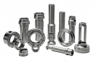
A buyer opens a drawing and sees a part that is round on one end and squared off on the other. The bore runs along the axis, and two cross holes have to line up with that bore. The first instinct is to send it to a turning shop.
Then the buyer looks again at the hex flats and the milled pad, and the instinct breaks down.
Most sourcing teams resolve that hesitation by splitting the part. One shop turns the blank and the OD, and another shop opens the pocket and drills the cross holes. The quotes come back higher than either single-process route, and nobody on the buyer’s side can explain why.
This article treats the milling vs turning decision as a costing problem rather than a vocabulary problem. It gives you three tests you can run in about two minutes, shows where the money actually goes, and lists the drawing changes that let one shop finish the part without a second grip.
The Difference That Decides Most Parts
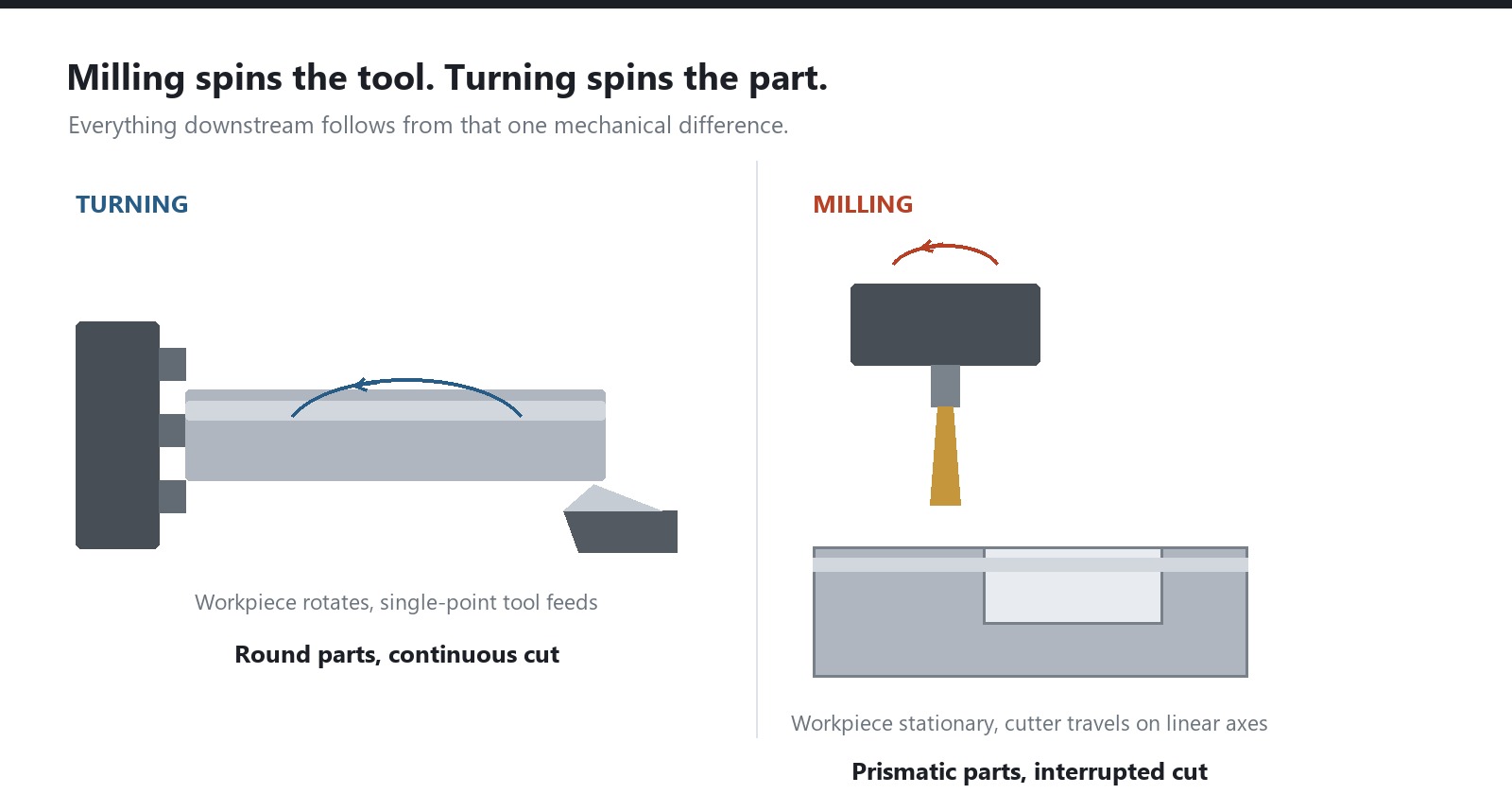
Milling rotates the tool. Turning rotates the workpiece.
In milling, a multi-flute cutter spins on a spindle and travels along linear axes, so the tool can reach any face the machine can position it over. In turning, the workpiece is held in jaws or a collet and rotated while a single-point tool feeds along a mostly radial and axial path.
That mechanical difference produces a clean capability split. Turning removes material continuously along a surface of revolution, which makes it efficient on shafts, bushings and flanges. Milling produces flat faces, pockets, slots and contours, because the cutter moves relative to a stationary frame.
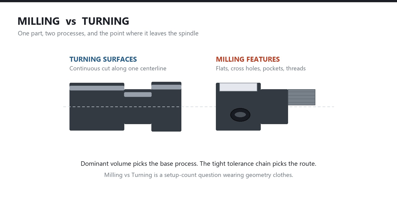
A part whose dominant volume sits around one centerline belongs on a lathe. A part whose dominant feature is a face or a pocket belongs on a mill. The milling vs turning difference therefore shows up in tool path and fixture design long before it shows up in the quote.
When a part needs both, the real question stops being which process to name and becomes how many times the part must be released.
The Three Tests That Decide the Route
Buyers often route a job by the most eye-catching feature. Production engineers route it by cost drivers, and they check three things in a fixed order.
Test 1: Is there an axis of revolution?
Draw an imaginary line through the part. If more than roughly half the volume sits symmetrically around that line, turning removes material faster per dollar than milling. Shafts, bushings, flanges and valve bodies pass this test easily.
If the dominant feature is a face, a pocket or a contour, milling owns the job. A bracket with two drilled holes is still a milling part, even though a lathe could technically make the holes.
The test measures dominant volume, not the presence of round features. That distinction matters, because a single cross hole is often enough to send an otherwise turning part to the wrong supplier. It is also the point where when to use CNC turning stops being a general topic and becomes a drawing-specific call.
Test 2: How tight is the tolerance chain between the two feature types?
This is the test designers skip most often, and it produces the most scrap.
Each move between machines forces a re-datum. The second operation has to establish where the first operation’s features actually sit, and that location carries the fixture’s own error. The re-datuming error stacks directly on top of the geometric tolerance you called out.
A cross hole that must meet a turned bore within 0.05 mm (0.002 in.) positional tolerance is achievable in one setup. Split the two features across two machines, and the same callout now absorbs probe error, fixture repeatability and chuck-to-chuck runout.
The part may still pass inspection. The process window narrows, and the shop has to slow down or inspect more often to hold it.
The working rule is simple: when a tight tolerance chain links a radial feature to a prismatic feature, keep both in one setup if the geometry allows it.
Test 3: How many setups does each route need?
Count setups, not operations. One setup equals one grip, one probe cycle and one first-article check.
A simple shaft is one setup, or two if both ends need work. A housing with features on five faces may need three or four setups on a 3-axis mill. A turned part with cross holes needs at least two, because the holes are milling work.
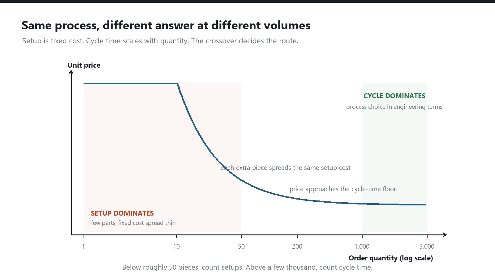
Setup is fixed cost, and it does not shrink with quantity the way cycle time does. At five pieces, setup dominates the price. At five thousand, cycle time dominates. This is why the same drawing can be quoted correctly as a mill job at prototype volume and a turned job at production volume.
Where the Money Actually Goes
Buyers compare hourly rates. Machinists compare setup hours. That mismatch explains most quote arguments.
A machining price is roughly setup time plus cycle time multiplied by quantity, plus material, inspection and margin. Only the rate is negotiable by shopping around, and the rest is structural.
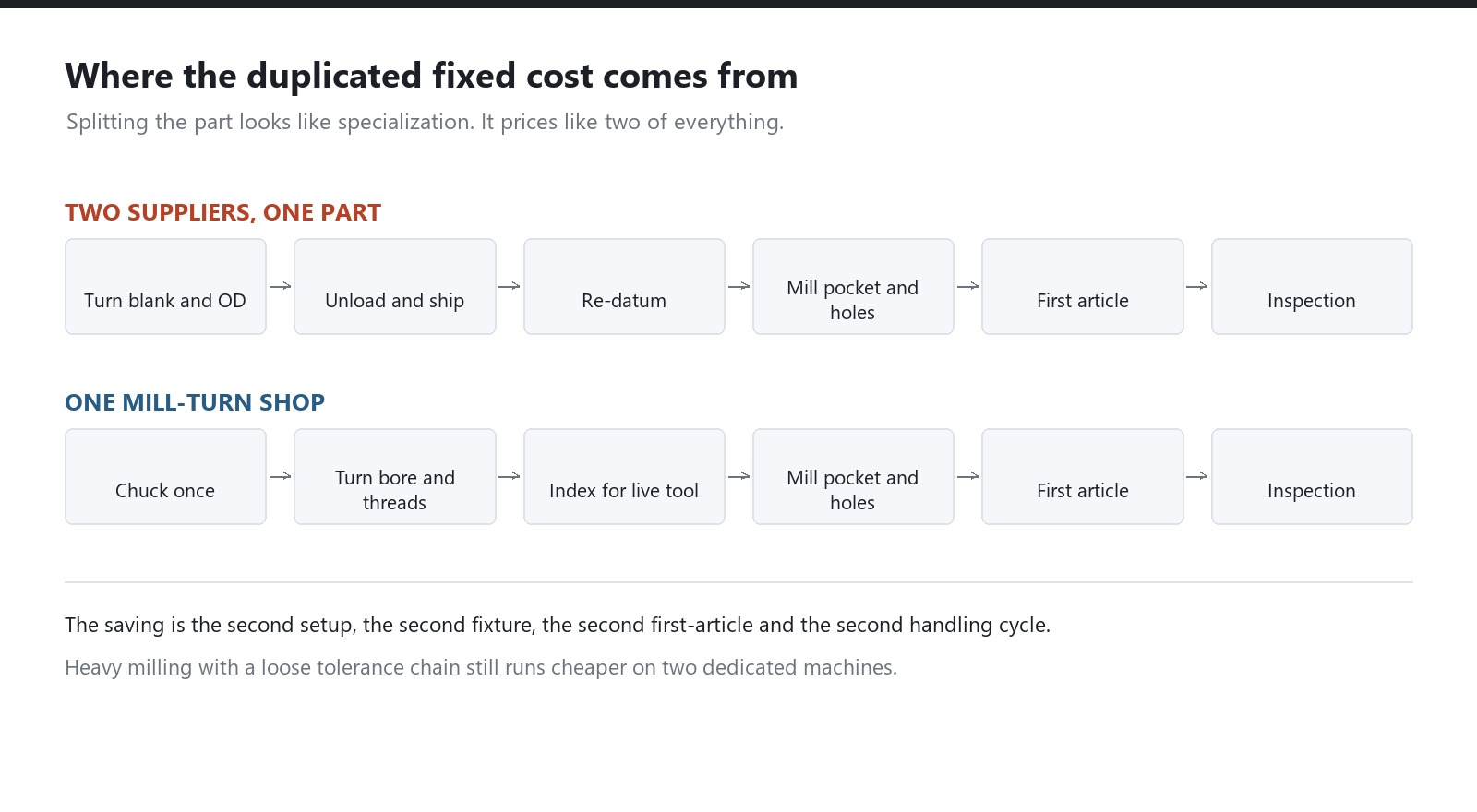
Setup dominates small lots. Every setup carries fixture work, clamping, probing, first-article verification and the risk of scrapping the first piece. Split a part between two suppliers, and it pays for two setups, two probe cycles and two first-article checks.
Cycle time dominates large lots. At volume, the process that removes material faster per dollar wins, and process choice becomes an engineering question again.
This is the level at which CNC milling process selection and lathe route selection start to change the total, rather than just the piece price.
Re-datuming is hidden cost. If the drawing gives the second shop no usable datum on the turned section, that shop has to create one, and the clarification costs schedule.
Freight and paperwork are not free either. Two suppliers mean two purchase orders, two receiving inspections and one more place for a dimensional discrepancy to appear after the part is already late.
None of these items is large on its own. Together they explain why a two-supplier split often quotes higher than a single-shop turn-mill package, even when the single shop charges a higher hourly rate.
Mill-Turn: One Grip, Two Processes
A mill-turn machine carries both a workpiece spindle and a live tool spindle. Many configurations add a second turret or a subspindle, which allows work on both ends of the part.
The practical effects are consistent. The part is gripped once, so the relationship between the turned bore and the milled pad is set by machine kinematics instead of by a fixture. There is no re-datuming step, so the positional callout only has to cover one machine’s error. Setup count drops, and that is where small-lot savings come from.
The trade-off is real. Live tooling is generally less rigid than a dedicated machining center spindle, so heavy pocketing is often faster on a 40-taper mill. Programming also takes longer, because tool path verification, collision checking and spindle synchronization consume engineering hours that appear in the programming line of a quote.
A mostly turned part with light milling wins clearly on mill-turn. A part with deep pockets and a loose tolerance relationship usually costs less on two dedicated setups.
What to Change in the Drawing
These are drawing-level edits, not redesigns. Each one helps a shop finish your part without a second trip through a fixture.
Give the turned section a usable datum. If a milled feature must relate to a bore, call the bore as a datum and dimension from it.
Keep the tight chain on one face. Stack interacting features so they can all be reached in one spindle orientation.
Call out spot faces on curved surfaces. A hole entering a cylindrical surface needs a flat, or the drill wanders before the point engages.
Set wall thickness by function, not by weight target. A 1.5 mm (0.060 in.) wall that exists only to hit a weight number may force light finishing passes across the whole job.
Skip tolerances on cosmetic chamfers, and mark which two or three dimensions are the actual fits. A drawing that tolerances everything equally tells the shop nothing about where to concentrate attention.
Ask for a design for manufacturability review before you redesign. An hour spent on the STEP file routinely removes a setup.
These edits are also the most direct way to reduce CNC machining cost on a mixed-feature part, because they act on setup count rather than on the hourly rate.
If you want a second read on where your part sits, send the drawing through our quote form and note which features must hold a tight relationship.
Conclusion
The milling vs turning decision reads like a geometry question, but it behaves like a setup question.
Three checks settle most parts. Look for an axis of revolution to pick the base process. Trace the tolerance chain across mixed feature types to decide whether the part may leave the spindle. Count setups to confirm the route still makes sense at your quantity.
The counterintuitive part is what happens when you split the work. Separating a turned part from its milled features looks like specialization, and it usually behaves like duplicated fixed cost. A shop with turn-mill capability removes that duplication on parts where a bore and a milled pad have to agree. Where the milling is heavy and the relationship is loose, dedicated machines remain the cheaper route.
For more process notes, read the XML-CNC blog, or review our mill-turn service and 5-axis capability.