During the Cold War, the Soviet Union faced a critical military challenge: their submarines were incredibly noisy and easily tracked by US sonar. The primary culprit was the loud cavitation noise generated by roughly machined propellers. The solution didn’t come from a new submarine design, but from a manufacturing breakthrough.
In the early 1980s, the Soviets acquired advanced 5-axis CNC milling machines from Toshiba. By utilizing this technology to machine flawlessly smooth, complex propeller blades, the noise levels plummeted, making the submarines nearly impossible to track.
This historic event proved a fundamental truth in manufacturing: 5-axis CNC machining is the ultimate gatekeeper for high-performance aerodynamic and hydrodynamic components. Today, this same technology is indispensable for manufacturing jet engine impellers.
In this comprehensive guide, we will explore the structural challenges of impeller manufacturing, why 5-axis CNC is the only viable solution, and how to overcome common programming issues like tool interference.
The Structural Challenges of Impeller Manufacturing
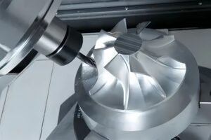
Impellers are the heart of aero-jet engines, responsible for compressing air to increase internal pressure for combustion. To achieve maximum aerodynamic efficiency, impellers feature highly complex geometries that present significant manufacturing hurdles.
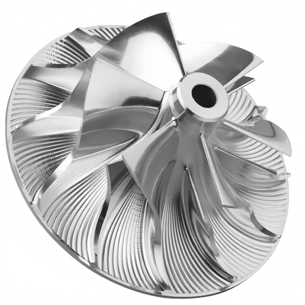
- Severe Blade Twist: Impeller blades are designed with large twist angles, leaving very narrow spaces between adjacent blades.
- Thin-Wall Instability: The blades are extremely thin and long. As a thin-wall component, they suffer from poor rigidity and are highly susceptible to deformation or chatter during cutting.
- Root Fillet Constraints: The narrow airflow channels require small-diameter cutting tools to machine the fillets at the blade roots, which significantly increases the risk of tool breakage.
Attempting to machine these features on a standard 3-axis machine is nearly impossible without multiple setups, which ruins precision and exponentially increases production time.
Why 5-Axis CNC is Essential for Complex Freeform Surfaces
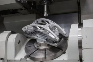
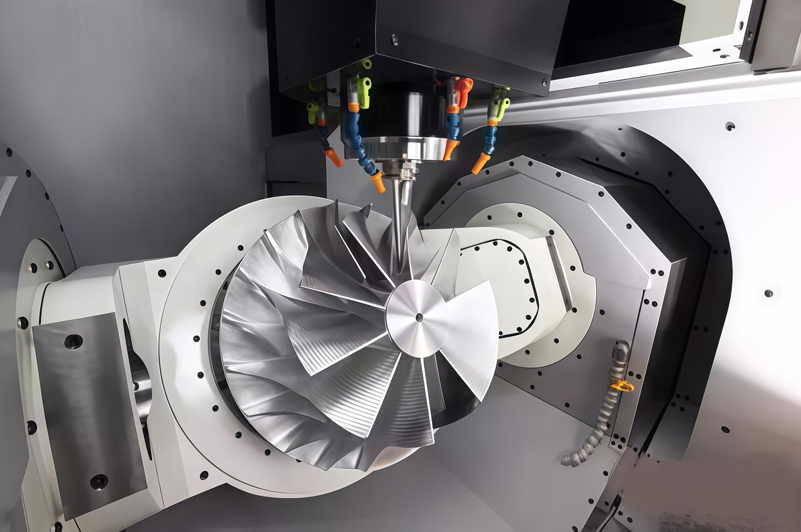
5-axis CNC machining centers, which add rotational A-axis and C-axis to the standard X, Y, Z axes, offer distinct technical advantages when processing aerospace components.
1. Avoiding “Zero-Point Cutting”
When machining complex curved surfaces on a 3-axis machine with a ball-nose end mill, the cutting efficiency at the very tip, the zero point, is virtually zero. This results in poor surface finishes that require manual polishing.
5-axis machining allows the tool axis to continuously adjust its angle relative to the workpiece, keeping the optimal cutting edge engaged at all times for a mirror-like finish.
2. Utilizing Shorter, More Rigid Tools
For deep cavities and tall, steep walls, 3-axis machines require excessively long tools, leading to tool deflection and overcutting.
5-axis machines tilt the tool or the table, allowing the use of much shorter, highly rigid tools to reach tight spaces, improving both accuracy and tool life.
Step-by-Step 5-Axis Machining Strategy & Tool Selection
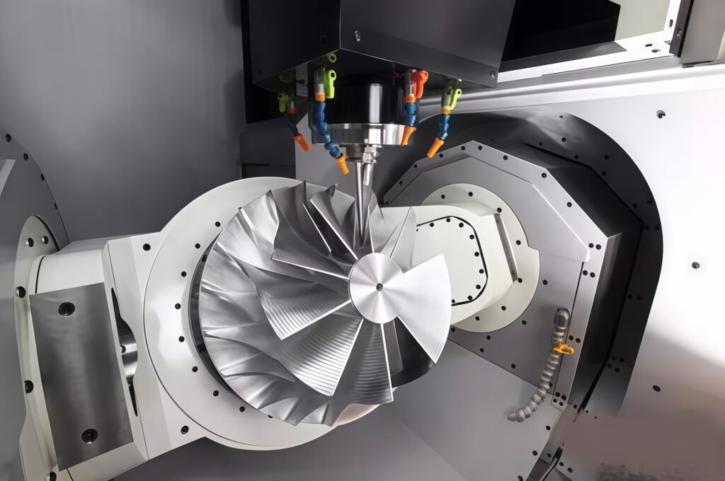
When programming a 5-axis impeller project in CAM software like UG NX, a structured approach is vital to maintain tight tolerances and prevent material deformation.
The standard process involves:
- Hub Roughing: Removing the bulk material using flat end mills.
- Channel Roughing: Clearing the narrow airflow channels between the twisted blades.
- Hub Finishing: Achieving the final surface tolerance on the central hub.
- Blade Finishing: Carefully profiling the thin-wall blades to their exact aerodynamic specifications.
Typical Tool Parameter Table for Impeller Cutting Cycles
| Step | Tool Diameter | Feed Rate (mm/min) | Spindle Speed |
| 1 | Φ10 | 5,000 | 8,000 |
| 2 | Φ10 | 2,000 | 8,000 |
| 3 | Φ8 R4 | 3,000 | 10,000 |
| 4 | Φ8 R4 | 5,000 | 15,000 |
| 5 | Φ8 R4 | 3,000 | 12,000 |
| 6 | Φ10 | 3,000 | 12,000 |
| 7 | Φ10 | 2,000 | 10,000 |
Data source: 5-Axis Jet Engine Impeller Machining Analysis
Case Study: Solving Tool Interference and Overcutting
Even with advanced software, the extremely narrow intake channels and long twisted blades of an impeller frequently cause programming errors.
In a recent simulation analysis, an overcutting phenomenon occurred during the blade finishing cycle. Due to the confined space, the tool shank interfered with the adjacent blade structure, causing a severe gouge that would have scrapped the part.
The Solution
By analyzing the kinematics in the CAM software and manually modifying the tool axis vector angles, specifically the A-axis rotation, the tool path was dynamically tilted away from the interference zone.
This slight angular adjustment eliminated the collision entirely, ensuring a flawless cut without compromising the required geometric tolerances.
Your Trusted Partner for Precision Hardware Components
Machining impellers and complex structural parts requires more than just high-end equipment; it demands deep engineering expertise and strict process control.
As an all-around hardware processing manufacturer, we specialize in delivering precision CNC hardware components and parts for demanding industries.
While we do not assemble complete finished machinery, our dedicated focus on component manufacturing ensures that every part we produce meets the most rigorous international standards.
Our advanced 5-axis capabilities allow us to machine complex geometries across a vast array of materials.
Whether your project requires standard metals like aluminum alloys and stainless steel, or you need components milled from advanced superalloys such as Inconel and Titanium, and high-performance engineering plastics like PEEK, POM, and PTFE, we have the technical know-how to deliver perfect parts on time.
Ready to optimize your next precision manufacturing project? Upload your 3D CAD files today, and let our engineering team provide a rapid, competitive quote for your complex hardware components.