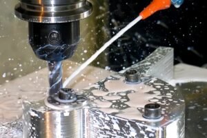
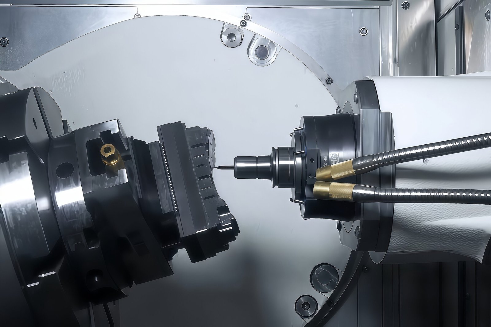
In high-precision manufacturing, modern industrial components are increasingly designed for lightweight performance, high mechanical strength, miniaturization, and optimized fluid dynamics. As engineering drawings incorporate organic freeform surfaces, angled deep cavities, and complex internal undercuts, traditional machining methods hit a physical bottleneck. Conventional 3-axis and 4-axis machine tools often struggle with tool interference, cumulative alignment errors from multiple setups, and severe chatter caused by extended tool reach.
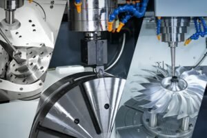
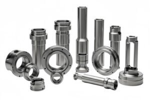
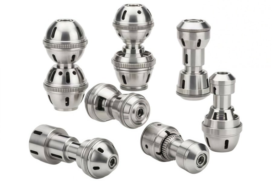
5-axis CNC machining serves as the definitive solution for manufacturing highly complex metal and plastic components. By continuously controlling tool orientation across five distinct motion axes, 5-axis technology allows manufacturers to produce intricate 5 axis cnc parts—from aerospace-grade titanium impellers and medical orthopedic implants to specialized industrial valve manifolds and ultrasonic transducer assemblies—with micron-level precision and minimal production lead times.
This comprehensive guide breaks down the spatial kinematics, physical hardware architectures, primary application scenarios, DFM (Design for Manufacturability) rules, cost structures, and B2B vendor evaluation criteria for producing world-class 5 axis cnc parts.
1. Deconstructing Spatial Kinematics: How 5-Axis CNC Machining Works
Understanding the capabilities of 5-axis manufacturing requires looking beyond two-dimensional and three-dimensional Cartesian planes into real-time spatial vector transformations.
Cartesian Coordinate System and Rotational Degrees of Freedom
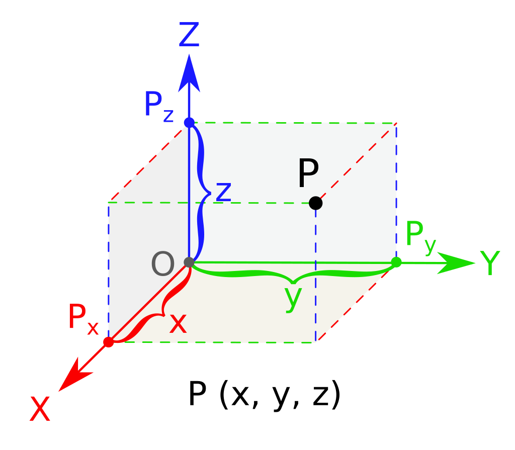
Standard 3-axis CNC milling machines operate within a basic X, Y, and Z Cartesian coordinate system:
X-axis: Controls horizontal (left/right) linear movement.
Y-axis: Controls longitudinal (front/back) linear movement.
Z-axis: Controls vertical (up/down) spindle movement.
In a standard 3-axis setup, the cutting tool axis remains strictly parallel to the Z-axis. Machining angled features or side faces requires stopping the machine, manually releasing the fixture, and repositioning the workpiece
5-axis CNC machines introduce two additional rotational degrees of freedom around the linear axes:
A-axis: Rotates or tilts around the X-axis (Pitch/Tilt).
B-axis: Rotates or tilts around the Y-axis (Roll).
C-axis: Rotates 360° continuously around the Z-axis (Yaw/Rotary).
By configuring combinations such as A/B, A/C, or B/C rotational axes alongside the X, Y, and Z linear axes, the machine maintains optimal cutting tool angles relative to the workpiece surface, easily bypassing obstacles and reaching tight geometries.
The Three Primary Hardware Architectures
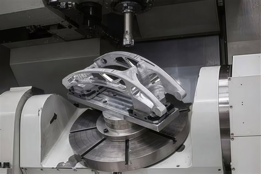
Depending on where the rotational axes are physically located, 5-axis machines fall into three primary design categories:
Trunnion / Table-Table (Double Rotary Table)
Structure: Both rotational axes (e.g., A and C) are integrated into the bottom rotary table. The spindle moves strictly along the X, Y, and Z linear axes.
Performance: High structural rigidity because the heavy spindle head does not tilt. However, weight capacity is limited because the workpiece tilts on the rotary table.
Best For: Small to medium-sized, ultra-precision 5 axis cnc parts with complex surfaces (e.g., medical implants, micro-impellers, precision hardware).
Swivel Head / Head-Head (Double Swivel Head)
Structure: Both rotational axes reside inside the spindle head, while the massive stationary worktable handles the workpiece weight.
Performance: Excellent for heavy raw materials weighing several tons. The articulation of the head allows large spatial reach, though torque and rigidity are slightly lower than trunnion setups.
Best For: Large aerospace structural frames, automotive die-casting mold inserts, and large wind turbine components.
Hybrid / Head-Table (Swivel Head + Rotary Table)
Structure: One rotational axis (e.g., B-axis) is located in the spindle head, while the second (e.g., C-axis) is integrated into the worktable.
Performance: Offers a balanced envelope size, excellent rigidity, and high rotational speeds on the table.
Best For: Large disk-shaped components, shafts, and mill-turn hybrid applications.
3+2 Positional Machining vs. Simultaneous 5-Axis Machining
Understanding the difference between 3+2 positional machining and full simultaneous 5-axis machining is critical when specifying requirements for custom 5 axis cnc parts:
3+2 Positional 5-Axis Machining
Mechanism: The machine uses two rotational axes to tilt the workpiece or spindle to a specific angle and locks the brakes. Then, standard 3-axis linear machining (X, Y, Z) executes the cut.
Characteristics: The rotational axes remain stationary during actual cutting. Programming is straightforward, calculation overhead is low, and setup rigidity is extremely high.
Best For: Prismatic multi-sided parts requiring drilling, tapping, or pocket milling on angled faces.
Simultaneous 5-Axis Machining
Mechanism: All 5 axes move continuously and synchronously in a single interpolated motion trajectory.
Characteristics: The cutting tool continuously adjusts its spatial orientation relative to the workpiece in real time. Requires RTCP algorithms and advanced CAM software.
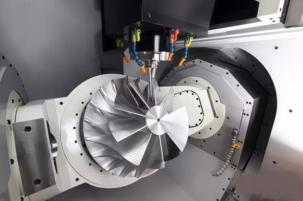
Best For: Organic freeform surfaces, complex impellers, fluid channels, and turbine blades requiring continuous, seamless surface finishes.
Key Technology: RTCP (Rotation Tool Center Point) / TCPM
In simultaneous 5-axis cutting, RTCP (Rotation Tool Center Point, also known as TCPM on Fanuc systems or M128 on Heidenhain controls) is the foundational control logic.
When a rotational axis tilts, the tip of a tool with finite length swings through a wide arc in physical space. Without real-time compensation, the tool tip would gouge or miss the part entirely.
How RTCP Works: The CNC controller dynamically calculates the spatial vector relationship between the tool length and rotational center points thousands of times per second. As the rotary table or swivel head tilts, the X, Y, and Z linear axes automatically execute high-speed micro-adjustments. The cutting tool tip stays locked onto the programmed trajectory regardless of how the machine head pivots, eliminating the need to re-program CAM toolpaths when switching tool lengths.
2. Prime Application Scenarios for 5 Axis CNC Parts
Not every part requires 5-axis processing. The highest economic and technical return on investment occurs when manufacturing high-value 5 axis cnc parts that fall into five primary categories:
1. Freeform Surfaces & Fluid Dynamic Components
Components designed for aerodynamics or hydrodynamics feature continuous, mathematically driven freeform curves with zero tolerance for steps or blend marks.
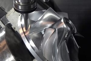
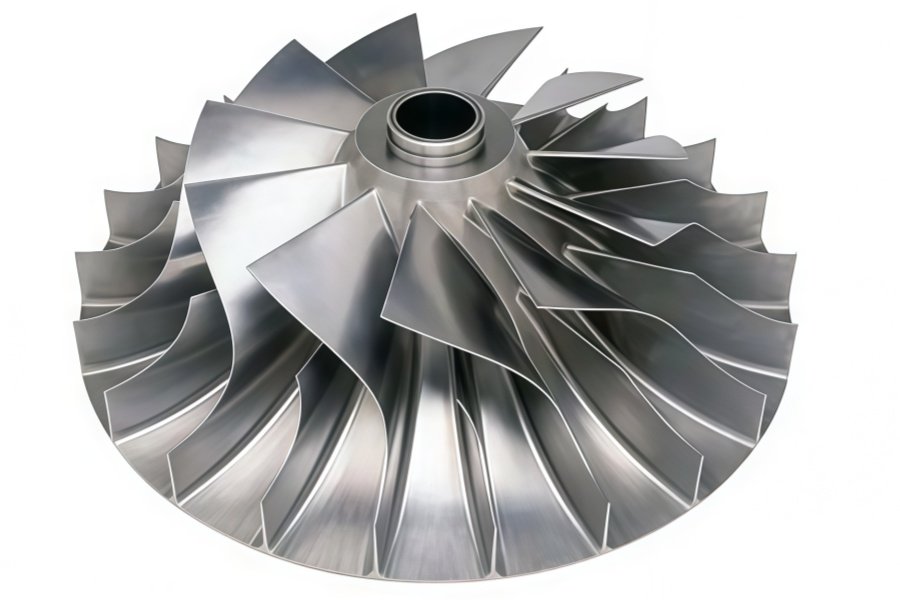
Typical Parts: Centrifugal compressor impellers, gas turbine blades, marine jet-pump propellers, and high-pressure fluid valve cores.
The 5-Axis Advantage: In 3-axis machining, ball-nose end mills cut at their bottom tip where cutting speed drops to zero, causing surface tearing and chatter. A 5-axis setup tilts the tool (e.g., by 15°), utilizing the sharp outer flank of the cutter where linear velocity is highest. This achieves surface finishes down to Ra≤0.4 μm without manual polishing.
2. Multi-Sided Polyhedrons & Angled Cavities
Parts featuring dozens of threaded holes, oil channels, dowel pin slots, and sealing grooves across multiple angled planes.
Typical Parts: Hydraulic valve blocks, heavy machinery gearbox housings, articulated robotic joint frames, and lightweight automotive powertrain housings.
The 5-Axis Advantage: Utilizing 3+2 positional machining, a single universal fixture holds the raw stock while all angled features are machined in a single continuous setup. This eliminates 80% of manual re-fixturing time and removes cumulative setup errors.
3. High-Precision Components with Strict GD&T Standards
Parts requiring micro-inch feature placement, concentricity, perpendicularity, and position tolerances (≤0.005 mm).
Typical Parts: Orthopedic hip/knee joint implants, medical sensor housings, ultrasonic transducer hardware, and high-end optical lens barrels.
The 5-Axis Advantage: Re-fixturing introduces alignment drift. Manufacturing precision 5 axis cnc parts in a “Done-in-One” process ensures all geometric features share a single, unified coordinate system.
4. Tough Materials & Deep Undercut Structures
Machining tough alloys like Titanium (Ti-6Al-4V), Inconel 718, or 17-4PH Stainless Steel produces massive cutting forces and thermal stress.
Typical Parts: Aerospace structural ribs, racing simulator (Sim Racing) aluminum mounting brackets, and automotive die-casting mold inserts.
The 5-Axis Advantage: Instead of using long, slender cutters that vibrate and break inside deep cavities, a 5-axis head tilts to avoid wall collisions, allowing the use of short, thick, high-rigidity end mills that handle aggressive material removal rates.
5. Micro-Carved Hardware & Premium Consumer Products
High-end consumer devices, beauty electronics, and specialty hardware demand pristine tactile finishes and sharp aesthetic contours.
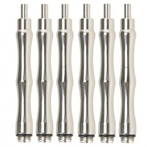
Typical Parts: Precision metal bases for diamond microdermabrasion tools and aesthetic equipment components (specifically custom-machined metal hardware and connectors, rather than complete devices), dual-curved bases for specialty coffee distributors and tampers, and anodized aluminum computer chassis.
The 5-Axis Advantage: Delivers flawless surface contours, tight tolerances, and intricate internal channels in a single manufacturing pass.
3. Maximizing ROI: 5-Axis Machining vs. Traditional Processes
To assist engineering and procurement teams in evaluating process trade-offs, the following comparison highlights key technical metrics across manufacturing methods:
| Feature / Metric | Standard 3-Axis Milling | 4-Axis CNC Milling | 5-Axis CNC Machining | Mill-Turn / Swiss Lathe |
| Number of Setups | 3 to 6 flips required | 2 to 4 rotations required | 1 setup (“Done-in-One”) | 1 setup (Turning + Milling) |
| Fixture Costs | Requires multiple custom jigs | Needs indexing rotary fixtures | Standard vise or zero-point grid | Standard collets / chucks |
| Geometric Limit | Top-down planes, simple slopes | Rotational profiles, angled holes | Freeform 3D curves, deep undercuts | Cylindrical bodies with milled flats |
| GD&T / Feature Accuracy | Vulnerable to re-clamping error | Moderate (single rotary axis) | Ultra-High (Positioning ≤0.005 mm) | Ultra-High (Concentricity ≤0.003 mm) |
| Tool Rigidness | Requires long cutters for deep pockets | Moderate | Tilts to use short, rigid tools | Uses short tools with high rigidity |
| Surface Finish (Ra) | Step-marks on curves (Ra1.6–3.2) | Ra0.8–1.6 | Mirror finishes (Ra0.2–0.4) | Turned Ra0.4, Milled Ra0.8 |
| Ideal Part Geometry | Cubes, plates, simple blocks | Shafts, 4-sided prismatic parts | Complex 3D geometries, deep cavities | Cylindrical, stepped shafts, fittings |
| NPI Lead Time | Long (waiting for custom jigs) | Moderate | Fast (no custom tooling required) | Moderate setup time, fast in production |
Core Strategic Benefits:
Eliminates Cumulative Setup Errors: Re-clamping a workpiece introduces human error, clamping deformation, and zero-point drift. A single 5-axis setup keeps all features relative to one origin point.
Dramatically Reduces Tooling Costs: Standardized zero-point clamping systems replace expensive, single-purpose multi-station fixtures, dropping upfront NPI (New Product Introduction) tooling costs.
Optimized Cutting Mechanics: Tilting the cutter maintains optimal surface speed, extending tool life, reducing chatter, and improving surface quality.
4. Advanced DFM Guidelines for Custom 5 Axis CNC Parts
Proactive Design for Manufacturability (DFM) lowers unit costs while improving quality. When designing 5 axis cnc parts, mechanical engineers should apply these core rules:
1. Standardize Internal Corner Radii
Issue: Non-standard or varying internal corner radii across deep pockets force frequent automatic tool changes (ATC) and custom cutter grinding.
DFM Solution: Standardize internal radii across the entire part (e.g., using R3 or R5 mm values). Design corner radii slightly larger than standard tool radii (e.g., specifying an R3.5 mm cavity corner for an R3 mm end mill) to prevent 90∘ tool engagement and vibration.
2. Design Workholding Tabs or Dovetail Slots
Issue: Machining 5 sides of a part in one setup requires secure clamping at the base without blocking cutter access to side walls.
DFM Solution: Add a 3–5 mm stock extension or a standard 45∘/60∘ dovetail slot at the base of the raw material. The zero-point vise clamps this sacrificed base tightly, leaving the rest of the part exposed for full 5-sided tool access. The base is easily faced off in a brief secondary operation.
3. Apply Rational Geometrical Tolerancing (GD&T)
Issue: Unnecessarily specifying ±0.002 mm tolerances across non-critical 3D surface profiles exponentially inflates cycle times and CMM inspection costs.
DFM Solution: Restrict tight tolerances (≤0.008 mm) strictly to critical bearing seats, alignment pin holes, and precision mating surfaces. Apply broader profile tolerances (±0.05–±0.1 mm) to aesthetic freeform surfaces.
4. Provide Adequate Spindle Clearance Angles
Issue: Although 5-axis heads swivel, the heavy physical spindle housing (often ∅150–250 mm) can collide with tall workpiece walls when reaching into narrow pockets.
DFM Solution: Maintain a minimum 15∘–20∘ conical clearance cone around deep pocket openings to ensure sufficient clearance for the swiveling spindle housing.
5. Cost Structure of Custom 5 Axis CNC Parts
Understanding the cost drivers behind 5-axis production enables clearer budget allocation and supplier price negotiations:
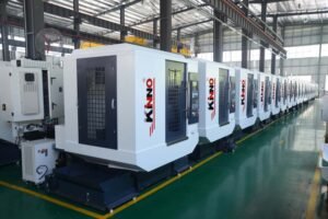
Capital Equipment Depreciation (35%): High-end 5-axis centers (from brands like DMG MORI, Hermle, or Makino) represent major capital investments. Machine hourly rates directly reflect this equipment overhead.
CAM Programming & Collision Simulation (25%): 5-axis motion carries real risks of high-speed spindle crashes. Generating multi-axis toolpaths (using software like HyperMILL or PowerMILL) and validating them through 100% digital anti-collision simulations (e.g., VERICUT) represents significant engineering labor.
Specialty Tooling & Workholding (15%): Advanced multi-layer coated carbide ball-nose cutters, taper end mills, and zero-point quick-change workholding systems contribute to ongoing operational costs.
CMM Inspection & Quality Control (15%): Complex 3D organic contours cannot be verified with calipers or micrometers. They require high-precision coordinate measuring machines (CMM) or 3D optical laser scanners to generate point-cloud inspection reports.
Raw Materials & Utilities (10%): High-grade raw bar stock/billets along with high-pressure internal coolant delivery power costs.
6. B2B Sourcing Guide: Evaluating 5 Axis CNC Parts Suppliers
When sourcing precision 5 axis cnc parts, relying solely on machine counts can be misleading. A capable manufacturing partner must balance physical machinery with rigorous engineering software and quality inspection infrastructure. Evaluate potential partners across four key pillars:
Pillar 1: Equipment Setup and Metrology Hardware
Confirm that the supplier operates modern trunnion or swivel-head 5-axis machining centers capable of holding required positional tolerances. Ensure they maintain a dedicated, climate-controlled inspection lab equipped with high-end CMM systems (such as ZEISS or Hexagon) to accurately verify complex spatial dimensions and freeform surfaces.
Pillar 2: CAM Depth and Advanced DFM Expertise
A top-tier manufacturer should actively review your CAD models and provide a detailed DFM feedback report within 24–48 hours. The supplier’s engineering team must demonstrate a complete CAM simulation pipeline (utilizing software like HyperMILL or PowerMILL) to perform 100% digital anti-collision checks before cutting metal.
Pillar 3: Multi-Material Capability and Process Integration
Look for suppliers capable of handling a broad range of raw stock—including aerospace Aluminum (6061-T6, 7075-T6), Stainless Steel (304, 316L, 17-4PH), Copper alloys, Titanium (Ti-6Al-4V), and engineering plastics (PEEK, POM, PTFE).
Leading custom hardware manufacturers (such asShenzhen Xinmingliang Technology Co., Ltd.) offer fully integrated production lines—combining 5-axis CNC milling, Swiss lathe turning, precision grinding, wire EDM, laser cutting, and sheet metal fabrication—to manage complex multi-part hardware projects seamlessly under one roof.
Pillar 4: Surface Finishing and Quality Systems
Complex 5 axis cnc parts frequently require post-processing like Type II/III anodizing, chemical passivation, sandblasting, electroplating, or laser engraving. Choosing a vendor capable of managing machining and surface finishing under a unified quality management system (ISO 9001 / IATF 16949) eliminates transport damage risks and guarantees end-to-end traceability.
Core Takeaways for Engineering & Procurement
5-axis CNC machining remains one of the most versatile methods for manufacturing high-complexity, high-precision metal and plastic components. By eliminating re-clamping errors, maintaining ideal cutting angles, and utilizing shorter, rigid tooling, 5-axis manufacturing turns challenging 3D CAD geometries into production-ready parts.
By applying smart DFM principles early in development and partnering with a full-service custom hardware manufacturer, engineering teams can optimize production costs, accelerate product launch cycles, and guarantee top-tier component reliability.